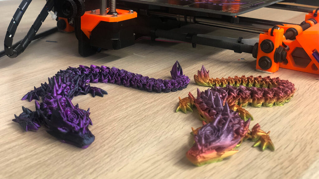
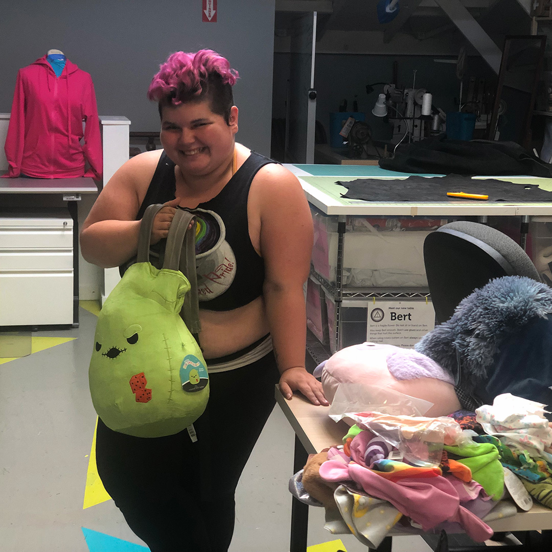
Ace Maker, Rene runs a small family business called Mischief Manor Makers that sells handmade goods both online and at local (and sometimes not so local) events like Folsom Street Fair, Surrender, and Play-X-Land at Cat Club Sf. Their inventory* changes frequently but includes kink and fetish gear like Custom Springbuck Horn Floggers, small pins with a wicked sense of humor, Custom Made Squishmallow Bags, and as of 6 months ago 3D printed items like their favorite Flexi Rose Dragons with articulated joints.
*Follow Rene on Tik Tok to learn more about Mischief Manor Makers and the things they like to make!
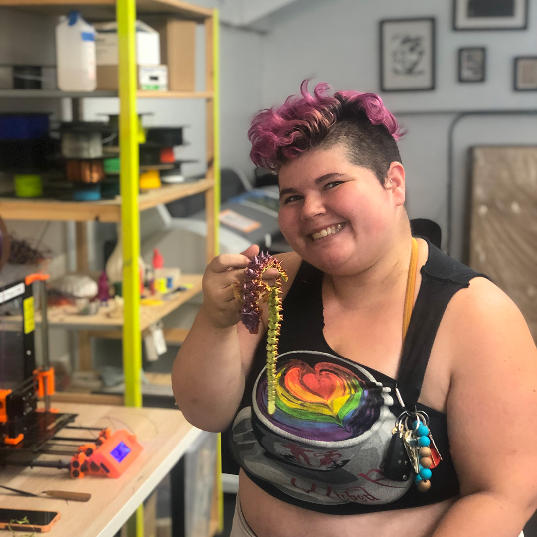
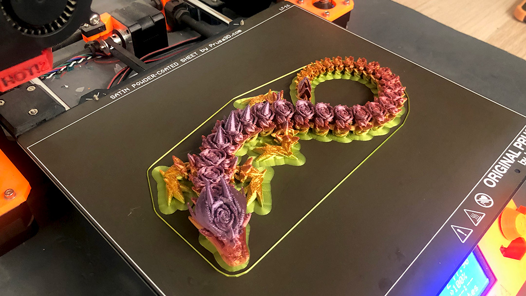
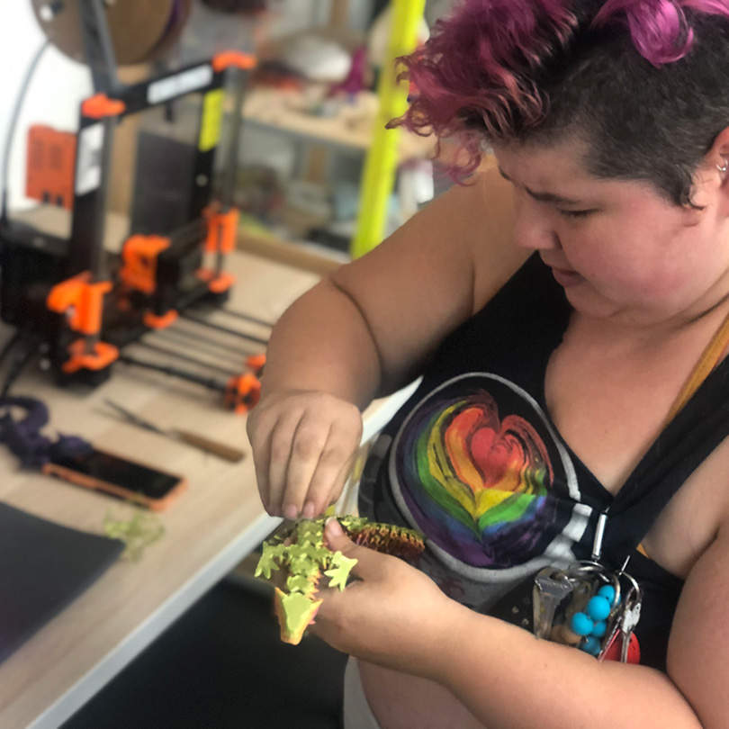
Rene shows off one of their freshly printed Flexi Rose Dragons!
Rene got into 3D printing when they were visiting one of their partners in Georgia who runs a small business similar to Mischief Manor Makers. He showed them the basics, helped them find a 3D printer to take home, and encouraged them to make it a part of their business.
To design this Flexi Rose Dragon, Rene found a pre-made base file online and customized it with roses and thorns (Thingiverse has many open source files available to use for free, but you can also purchase premade files from places like Etsy).
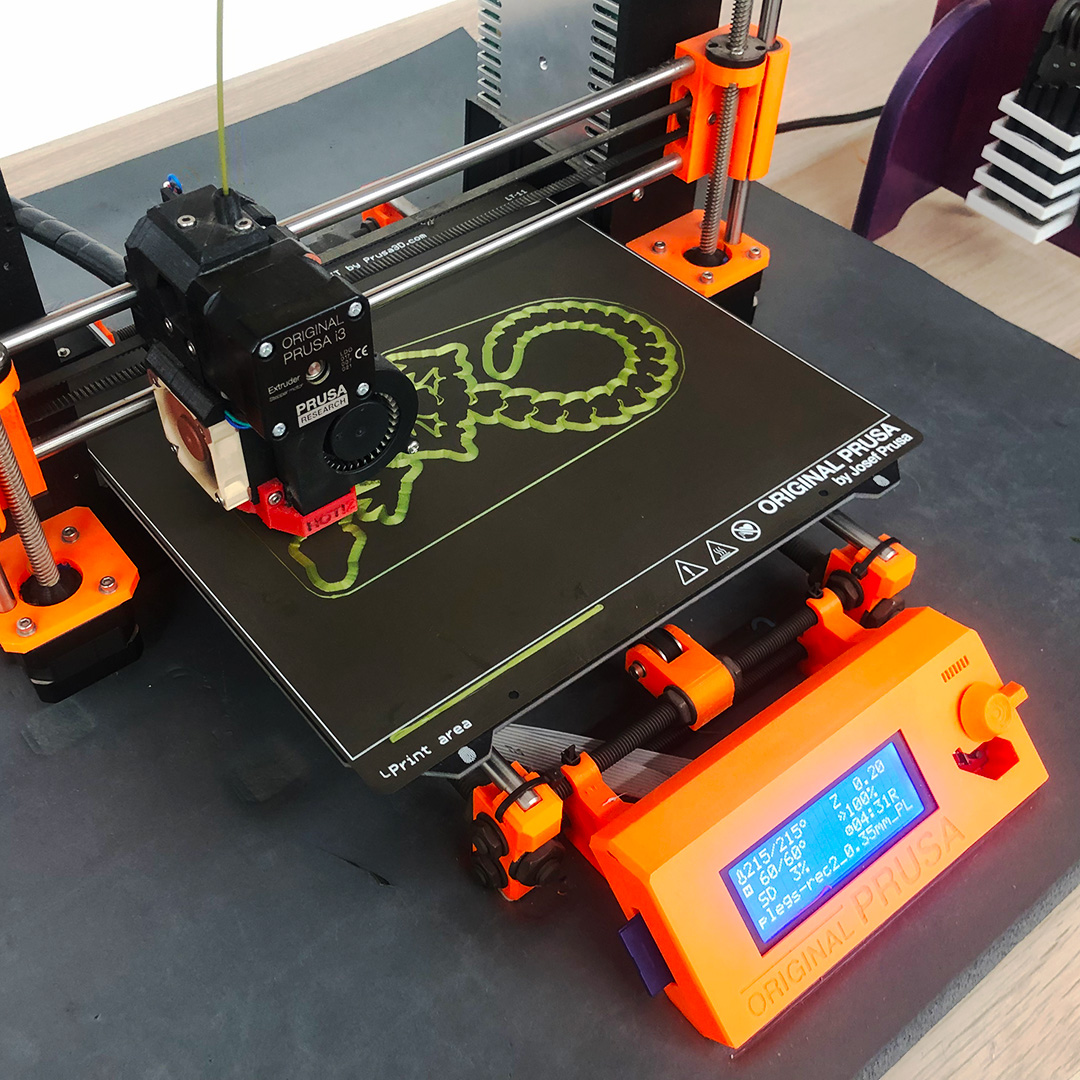
For a shiny multicolor effect, Rene works with a special gradient silk filament which is slightly more delicate and little bit trickier to print with than standard PLA filament.
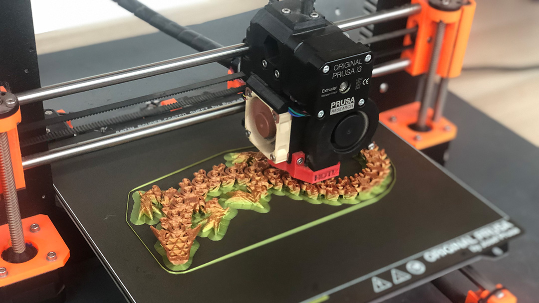
Each print begins with a brim—a stable base layer that keeps the Flexi Rose Dragon in place preventing it from slipping off the build sheet or collapsing during the job. When the dragon has finished printing, Rene will remove the brim to release the articulated joints that allow the Flexi Rose Dragon to move. They’ve learned through trial and error that printing a brim is critical even though it adds an additional 20 minutes to the already 4.5 hour printing time.
A strong foundation is the key to printing a successful Flexi Rose Dragon. The brim provides stability while printing flexible objects, but it will need to be removed at the end to release the “joints.”
Once they’ve made sure the brim has printed correctly, Rene likes to head up to the Ace Textiles Studio to work on other merchandise like their Custom Made Squishmallow Bags. They also check on their print at regular intervals to make sure everything runs smoothly.
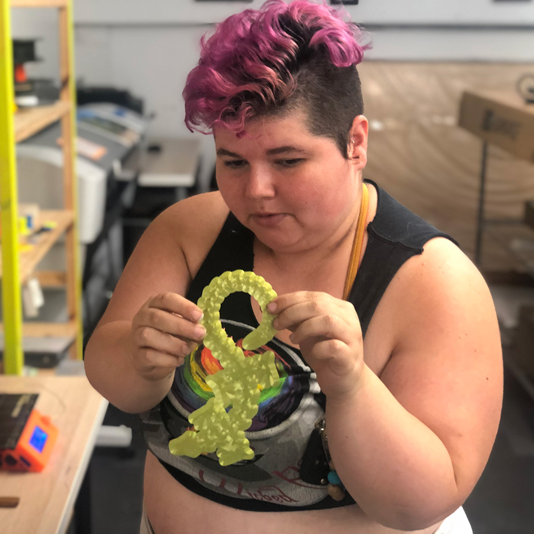
Rene’s daughter came up with the idea for bags made from Squishmallow Plushies.About half way through the print the topographical rose motif starts to emerge!It’s time to unleash the Flexi Rose Dragon from the build sheet.To complete the dragon Rene will peel back the green brim on the underside of the dragon.Shedding the brim takes a little bit of patience but its totally worth it!Two completed Flexi Rose Dragons on the prowl at the Ace Makerspace 3D Printing station.
Rene’s tips for folks curious about getting started with 3D Printing:
Check out Thingiverse for inspiration and pick something that excites you
Find community! Places like Ace Makerspace are great because there’s a built in support system if you need help troubleshooting as your starting out
If you plan to dive in and purchase your own 3D Printer, go for a well known brand because there is more documentation and technical support if something goes wrong
Hi, my name is Mark. I’ve been a member of ACE for almost 9 years. There’s been three things on my To-Do list gnawing at my psyche for some time:
Learn about Raspberry Pi microprocessors through Internet of Things (IoT) applications.
Get hands-on experience with Artificial Intelligence.
Learn the popular Python programming language.
Why these? Because computers are getting smaller while getting more powerful; Artificial Intelligence (AI) is running on ever smaller computers; and Python is a versatile, beginner-friendly language that’s well-documented and used for both Raspberry Pi (RPi) and AI projects.
I’ve been working in computer vision, a field of AI, for several years in both business development and business operations capacities. While I don’t have a technical background, I strive to understand how the engineering of products & services of my employers works in order to facilitate communication with clients. Throughout my career I’ve asked a lot of engineers a lot of naive questions because I’m curious about how the underlying technologies come together on a fundamental level. I owe a big thanks to those engineers for their patience with me! It was time for me to learn it by doing it on my own.
Computer Vision gives machines the ability to see the world as humans do – Using methods for acquiring, processing, analyzing, and understanding digital images or spatial information.
In starting on my learning journey I began a routine of studying at our ACE Makerspace coworking space every week to be around other makers. This helped me maintain focus after the a pandemic induced a work-from-home lifestyle that left me inhibited by a serious brain fog.
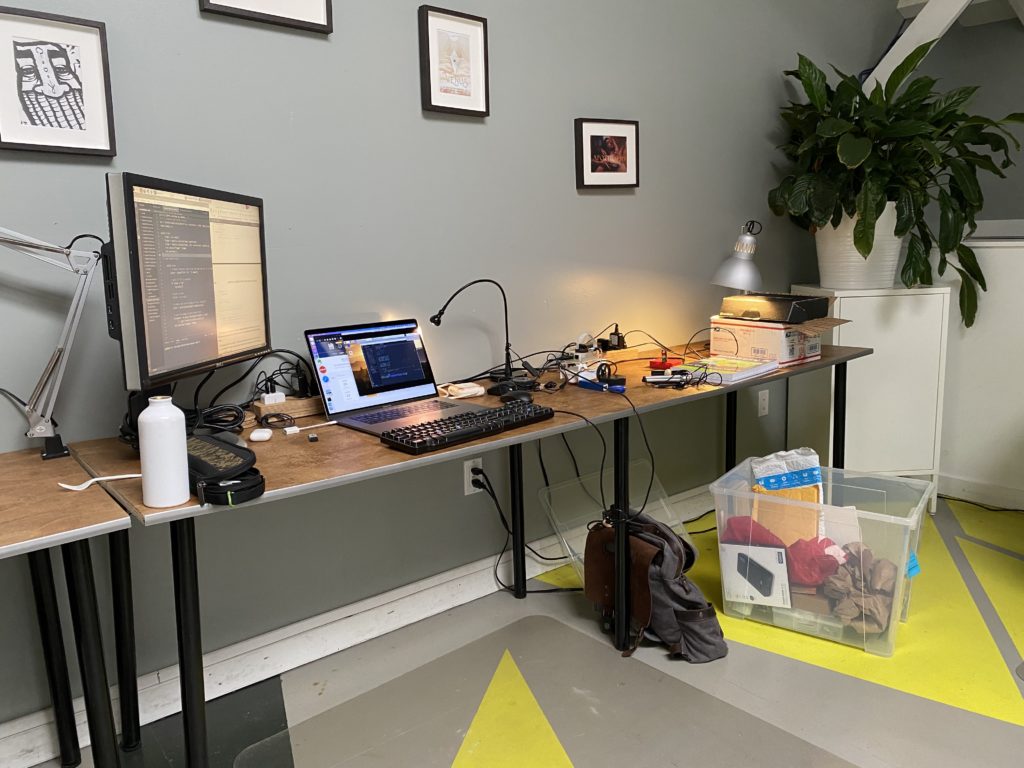
My work environment at ACE Coworking
OpenCV (Open Source Computer Vision Library) is a cross-platform library of programming functions mainly aimed at real-time computer vision. AMONG MANY COMPONENTS It includes a machine learning library as a set of functions for statistical classification, regression, and clustering of data.
Fun Fact: Our ACE Makerspace Edgy Cam Photobooth seen at many ACE events uses an ‘Edge Detection’ technique also from the OpenCV Library.
A self-paced Intro to Python course came first. Then came a course on OpenCV which taught the fundamentals of image processing. Later still came tutorials on how to train a computer to recognize objects, and even faces, from a series of images.
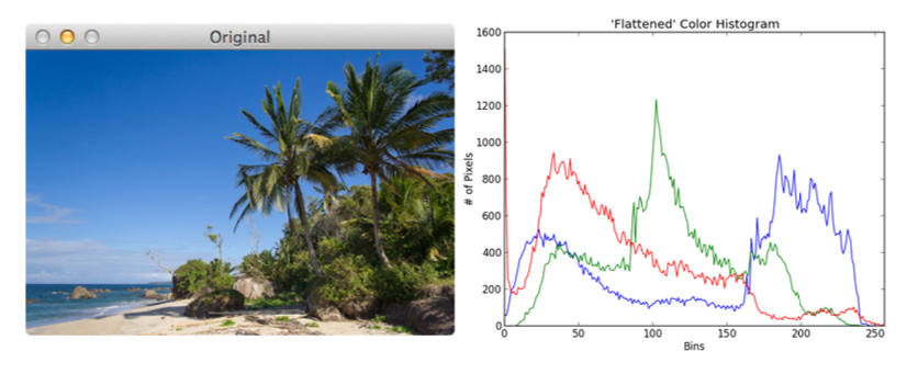
Plotting the distribution of color intensities in the red, green, and blue color channels
3D scatter plot of distributions of grouped colors in images
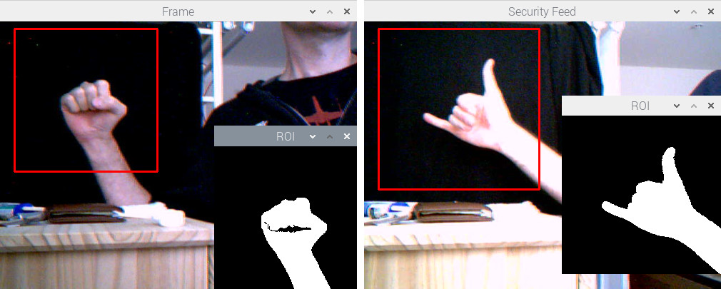
A binary mask to obtain hand gesture shape, to be trained for gesture recognition
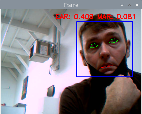
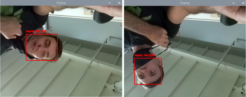
Notice the difference in probabilities associated with the face recognition predictions when the face is partially occluded by face mask
Eventually, I moved onto more complex projects, including programming an autonomous mini robot car that responds to commands based on what the AI algorithm infers from an attached camera’s video feed – This was real-time computer vision! There were many starter robot car kits to choose from. Some are for educational purposes, others come pre-assembled with a chassis, motor controllers, sensors, and even software. Surely, this was the best path for me to get straight into the software and image processing. But the pandemic had bogged down supply chains, and it seemed that any product with a microchip was on backorder for months.
A backlog of cargo ships waiting outside west coast ports as a symbol of supply chain issues
I couldn’t find a starter robot car kit for sale online that shipped within 60 days and I wasn’t willing to wait that long.And I didn’t want to skip this tutorial because it was a great exercise combining the RPi, AI, and Python programming triad. ACE Makerspace facilities came to the rescue again with the electronics stations and 3D printers which opened up my options.
I learned a few things working at computer vision hardware companies: Sometimes compromises are made in hardware due to availability of components; Sometimes compromises are made in the software due to the lack of time. One thing was for sure, I had to decide on an alternative hardware solution because hardware supply was the limiting factor. On the other hand, software was rather easy to modify to work with various motor controllers.
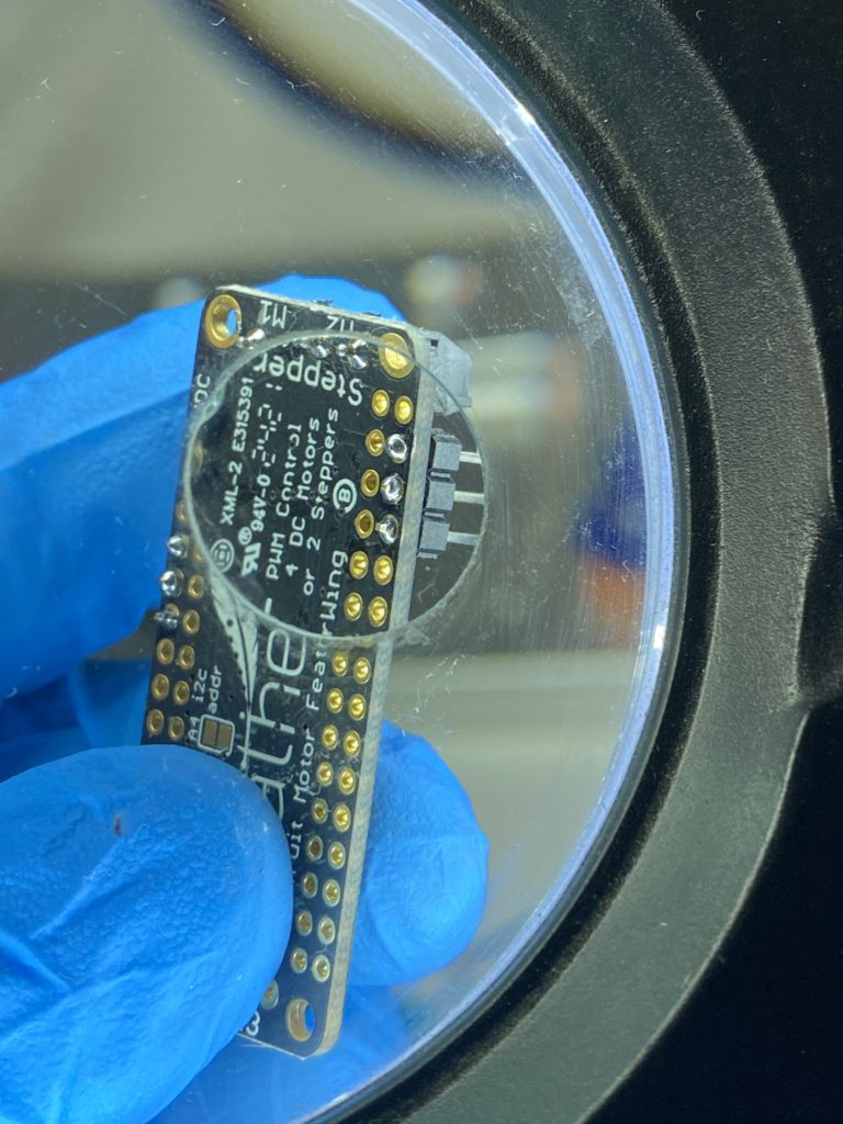
So after some research I decided on making my own robot car kit using the JetBot reference design. The JetBot is an open-source robot based on the Nvidia Jetson Nano, another single board computer more powerful than the RPi. Would this design work with the RPi? I ordered the components and shifted focus to 3D printing the car chassis and mounts while waiting for components from Adafruit and Amazon to arrive. ACE has (2) Prusa 3D printers on which I could run print jobs in parallel;
When the parts arrived I switched over to assembling and soldering (and in my case, de-soldering and re-soldering) the electronic components using ACE’s electronics stations equipped with many of the hand tools, soldering materials, and miscellaneous electrical components. When fully assembled, swapping in the Raspberry Pi for the Jetson Nano computer was simple and it booted up and operated as described on the JetBot site.
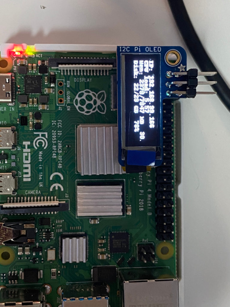
SolderingIt’s ALIVE! with an IP address that I use to connect remotely
The autonomous robot car starts by roaming around at a constant speed in a single direction. The Raspberry Pi drives the motor controls, operates the attached camera, and marshals the camera frames to the attached blue coprocessor, an Intel Neural Compute Stick (NCS), plugged into and powered by the Raspberry Pi USB 3.0 port. It’s this NCS that is “looking” for a type of object in each camera frame. The NCS is a coprocessor dedicated to the application-specific task of object detection using a pre-installed program called a MobileNet SSD – pre-trained to recognize a list of common objects. I chose the object type ‘bottle’.
“MobileNet” because they are designed for resource constrained devices such as your smartphone. “SSD” stands for “Single-shot Detector” because object localization and classification are done in a single forward pass of the neural network. In general, single-stage detectors tend to be less accurate than two-stage detectors, but are significantly faster.
The Neural Compute Stick’s processor is designed to perform the AI inference – accurately detecting and correctly classifying a ‘bottle’ in the camera frame. The NCS localizes the bottle within the camera frame and determines the bounding box coordinates of where in the frame the object is located. The NCS then sends these coordinates to the RPi; The RPi reads these coordinates, determines the center of the bounding box and whether that single center point is to the Left or Right of the center of the RPi’s camera frame.
Knowing this, the RPi will steer the robot accordingly by sending separate commands to the motor controller that drives the two wheels:
If that Center Point is Left of Center, then the motor controller will slow down the left wheel and speed up the right wheel;
If that Center Point is Right of Center, then the motor controller will slow down the right wheel and speed up the left wheel;
Keeping the bottle in the center of the frame, the RPi drives the car towards the bottle. In the lower-right corner of the video below is a picture-in-picture video from the camera on the Raspberry Pi. A ‘bottle’ is correctly detected and classified in the camera frames. The software [mostly] steers the car towards the bottle.
Older USB Accelerators, such as the NCS (v1), can be slow and cause latency in the reaction time of the computer. So there’s a latency in executing motor control commands. (Not a big deal for a tabletop autonomous mini-car application, but it is a BIG deal for autonomous cars being tested in the real world on the roads today.) On the other hand, this would be difficult to perform on the RPi alone, without a coprocessor, because the Intel NCS is engineered to perform the application-specific number-crunching more efficiently and while using less power than the CPU on the Raspberry Pi.
Finally, I couldn’t help but think that there was some irony in this supply chain dilemma that I had experienced while waiting for electronics to help me learn about robots; Because maybe employing more robots in factories will be how U.S. manufacturers improve resilience of supply chains if these companies decide to “onshore” or “reshore” production back onto home turf. Just my opinion.
Since finishing this robot mini-car I’ve moved on to learn other AI frameworks and even training AI with data in the cloud. My next challenge might be to add a 3D depth sensor to the robot car and map the room in 3D while applying AI to the depth data. A little while back I picked up a used Neato XV-11 robot vacuum from an ACE member, and I might start exploring that device for its LIDAR sensor instead.
Let me know if you’re interested in learning about AI or microprocessors, or if you’re working on similar projects. Until then, I’ll see you around ACE!
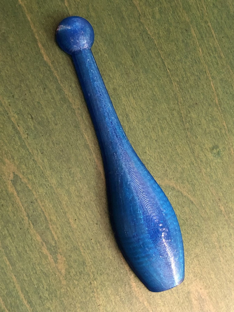
This is a 4 inch long juggling club model with a pocket for a neodymium magnet which transmogrifies it into a fridge magnet with enough power to hold a sleeping baby to the freezer door.
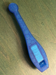
I spent more time on the pocket than the rest of it. When printed in pleasantly flexible TPU a 25x10x3mm magnet slips easily into the pocket and then stays there. There is .75mm of TPU between the magnet and the outer edge to temper the pull and prevent damage to the magnet. I used N52 strength magnets as they are stronger than the lower numbered ones.
I doubt many people want this exact shape so I’ve included some files to work from to make your own thing. Along with the completed club file I’ve uploaded the file just for the magnet pocket. You can use this to cut the magnet pocket in anything you want for your fridge. STL & STEP formats included in this zip archive.
If you open these parts in Fusion360 or other app of your choice it should be obvious how to make this work for other shapes. If it’s not just post on Slack and ask for guidance.
Ted Huller is a long-time Ace member and also Ace’s resident 3D Printing Steward. I’m Carter Jenkins, and I had the chance to talk with Ted about his history with Ace as well as some recent work he has done.
Ted’s History with Ace
Ted is a long-time friend of Ace Executive Director Rachel Crafty, but Ted’s story begins before Rachel was in that role. Ted works in a laboratory, and throughout his working process, he sometimes finds that he needs to make custom-built parts in order to fulfill certain jobs. He normally would make these parts out of wood, (Ted is a master woodworker) but one day the job required a small beaker holder that was too fine to make with wood. Hearing about Ace’s 3D printing workspace, Ted decided that he should learn some basic skills in 3D printing so that he could handle situations like these. He admits the process wasn’t very smooth, but in the end, he had a working product, and that experience made Ted very interested in 3D printing as a whole.
Fast forward a few years, and Ted became a regular Ace member. He still did woodworking at home, but the Ace makerspace had become his new home for metalwork and some 3D printing. Ted quickly got his own 3D printer at home, meaning that his interactions with Ace slowly dwindled as his needs for printing materials shrunk. One day, however, former 3D printing steward Matt stepped down, leaving the position open to anyone in the Ace community. After some deliberation, Ted decided that he should give something back to the Ace community, and with his new expertise, Ted became the printing steward.
The 3D Printing Space at Ace
The 3D printing space is shared with a multipurpose space that houses the electronics lab, a couple of workstations, and the big format paper printer. This room is known as the Clean Fabrication room. There are two Prusa-brand 3D printers, which Ted calls “the Ford F-150 of printers. There’s a lot of them, they’re not the most sophisticated, but they’re pretty darn reliable and thought out.” There’s also a nearby computer dedicated to preparing files for the printers. The printers don’t need a computer to run, but makers will often find that it helps to be able to do last-minute manipulations to the 3D object files.
The Slack community for 3D printing at Ace has members in the hundreds, and pretty much all questions and discussions happen over Slack. Ted considers it the most efficient way to ask, read, and answer questions; he encourages new members to use Slack for almost all of their communications.
An Example of Ted’s Work
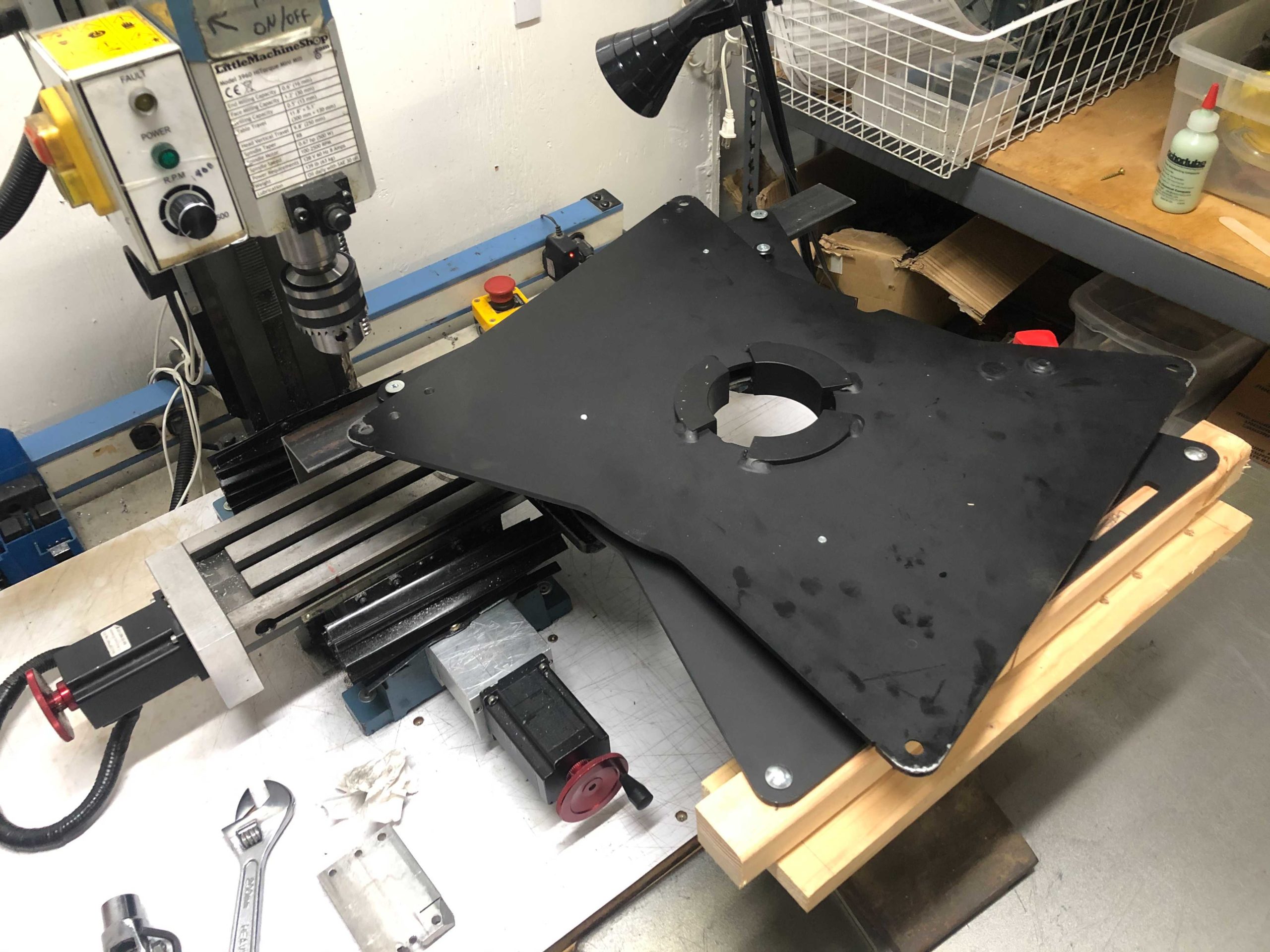
Some in-progress work being done at the Ace metal mill
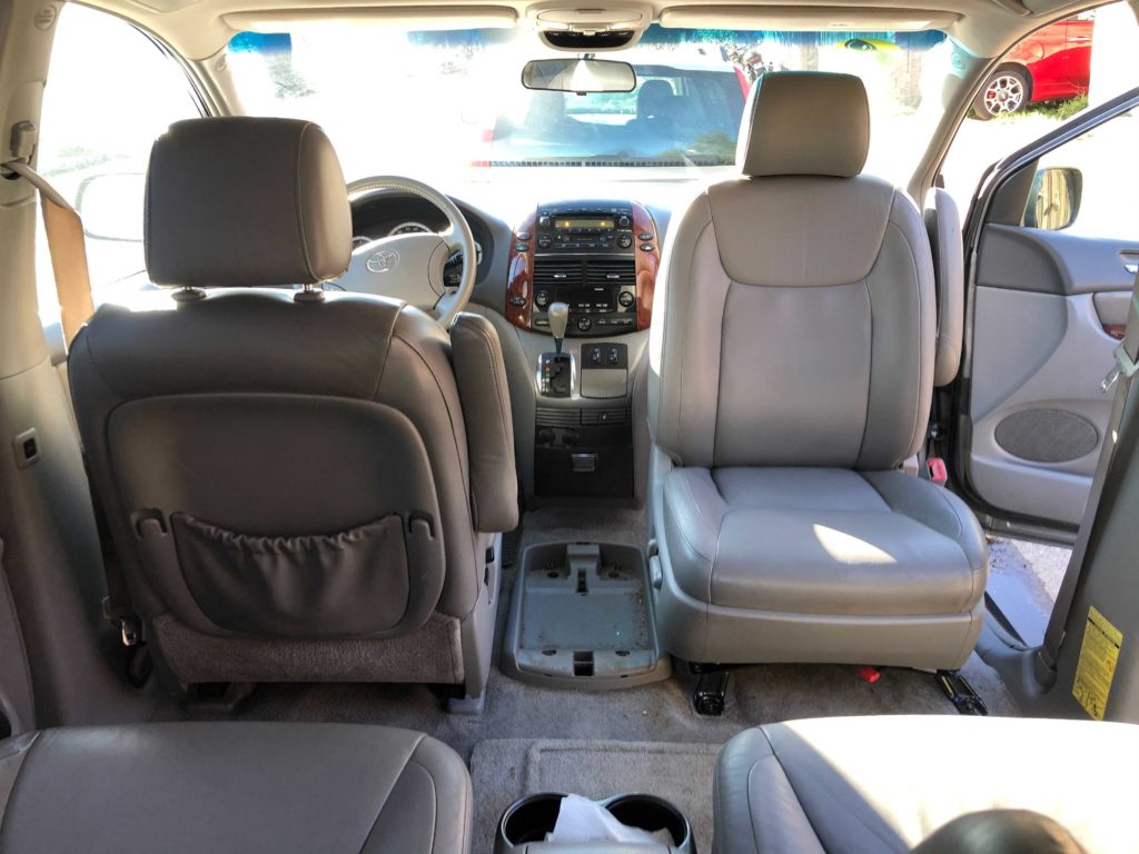
Ted and his wife recently bought an old minivan so they can go camping without having to deal with tents. The Toyota they bought was almost perfect for this purpose, except for one thing. The two of them both found the minivan to be a little too small to have both front seating and bed arrangements, so they looked into having adaptable seats that could swivel and lie down to make beds. The Toyota’s seats, however, were bolted to the floor in such a way that commercial seat-adjusting kits wouldn’t work. With no other options, Ted turned to his making skills to fabricate a “captain’s chair,” similar to those found in commercial RVs.
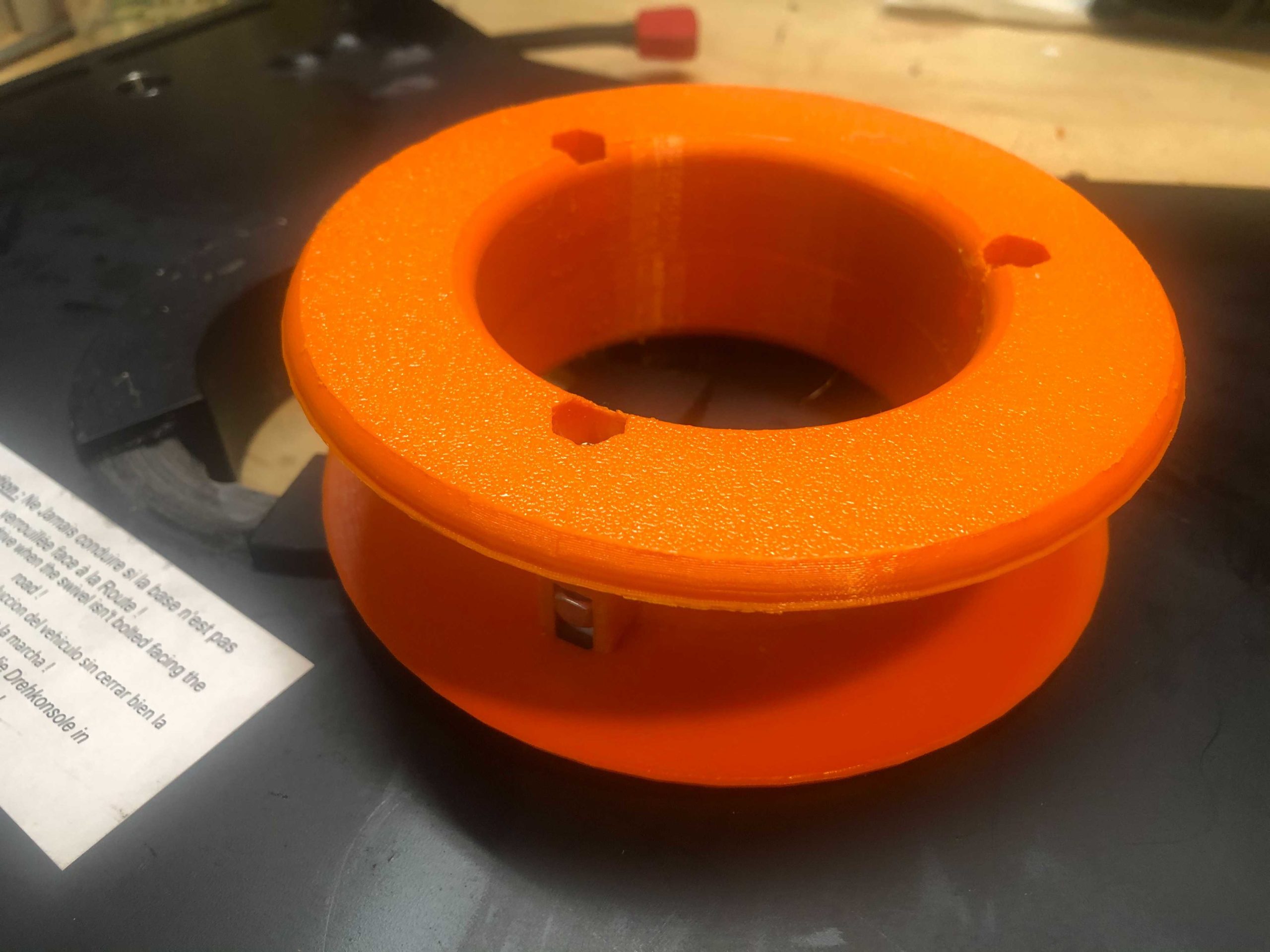
Ted started with drilling out a swivel plate and holes in the floor of the van, making sure to line them up precisely by means of the metal mill at Ace. The actual process of making the seat swivel wasn’t that difficult, but Ted encountered another problem soon after. Modern-day seats in cars and vans have lots of electrical wiring leading into them, whether it’s for operating a heater or controlling the seat’s back-and-forth movement. Ted found that the wires in the seat were dangerously close to shearing themselves on some exposed metal left by the drill holes, which would cause all sorts of maladies if not addressed properly. To solve this problem, he 3D printed a large plastic washer that bolts onto the wire hole. This means that instead of the wires dragging on sharp metal edges, it’s protected by a layer of comparably soft plastic. There were other little 3D-printed objects that Ted made, such as protective sheaths for the wire connectors.
An example of a bushing used in the project
Interestingly, Ted’s neighbor was going through a similar process with a van of their own at around this time. They had also encountered the same wire-cutting problem, and since Ted had just fitted the washer he offered to print a duplicate for his neighbor. With about a dollar’s worth of filament, Ted solved his neighbor’s problem.
Closing
Ted will continue to make and create at Ace for a long time. There are no big projects in his immediate future, but before our talk ended Ted told me that he was looking forward to, “training some more people, getting them ready, and seeing what people are going to 3D print.” I’m Carter Jenkins and thank you for reading.
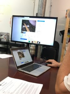
Last night, I went to my first 3D Printing 101 class at AMT.
It took me about a month to finally let go of all my excuses and commit to this intro class, but I’m glad I did. As a new member, I was sold on how much I could gain from the facilities and all the new things I could learn… but I knew there would be a HUGE learning curve with learning CAD/CAM design software and I wasn’t sure if I’d be patient enough to stick with it to be honest.
If you’re a new member, and have had the same doubts as I have, don’t fear, there are great people, instructors, and resources here every step of the way. This 3D Printing class was hosted by the amazing Volunstructor (Volunteer Instructor) Matt Keveney, and he definitely knows his stuff.
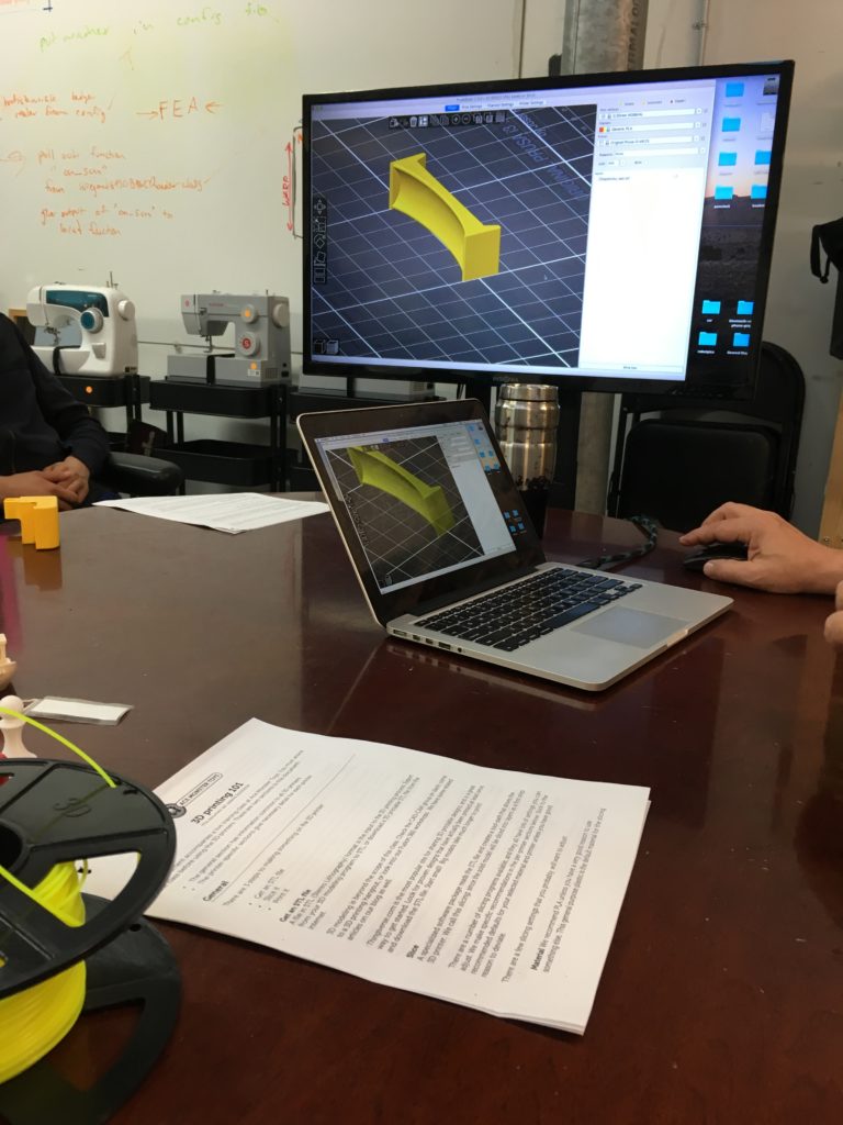
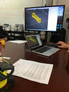
The class is about 2-hours long with the first half focused on the foundational concepts and printer settings, and the second half on the basics of Fusion 360 and a print project suggested by the class.
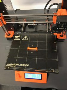
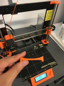
For this session, we decided to print out a Chop Stick Rest.
Our concept:
Our model:
It looks simple, but it took about 20 minutes to print out.
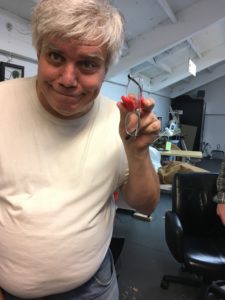
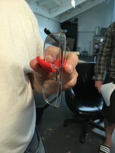
Matt even showed us one of the projects he’s been working on.
It’s an Eye Glass Holding Mount!
3D printing has been trending for a while now and I’ve always been fascinated with the creative possibilities, and now I know enough to get started.
After reading through this I hope you’re less intimidated and more inspired. Go out and make something– We are a Makers space after all.
Don’t forget to look at the calendar for all the new upcoming events:
https://www.meetup.com/Ace-Monster-Toys/events
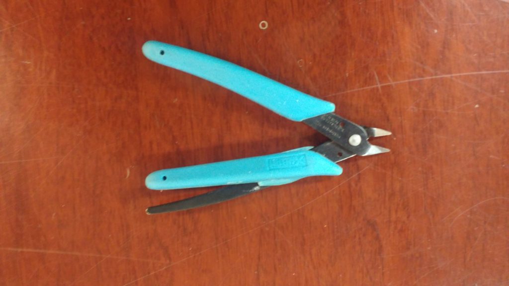
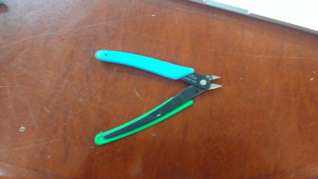
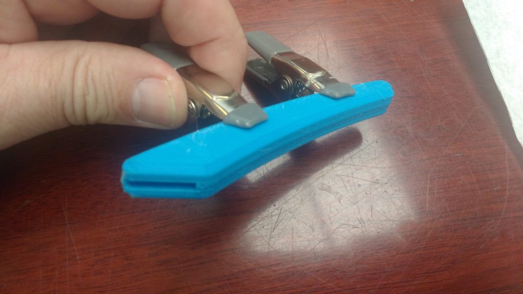
This is what our filament nippers looked like in 3D printing.
The work fine, but one of the rubber grips has almost split in two.
A few weeks ago, Evan made a valiant effort at saving them:
But, alas, the patch quickly broke off.
It’s a great excuse for another Fusion 360 3D printing article!
I’ll make the replacement in PLA. It won’t be squishy like the original, but it’ll be more comfortable than the bare metal.
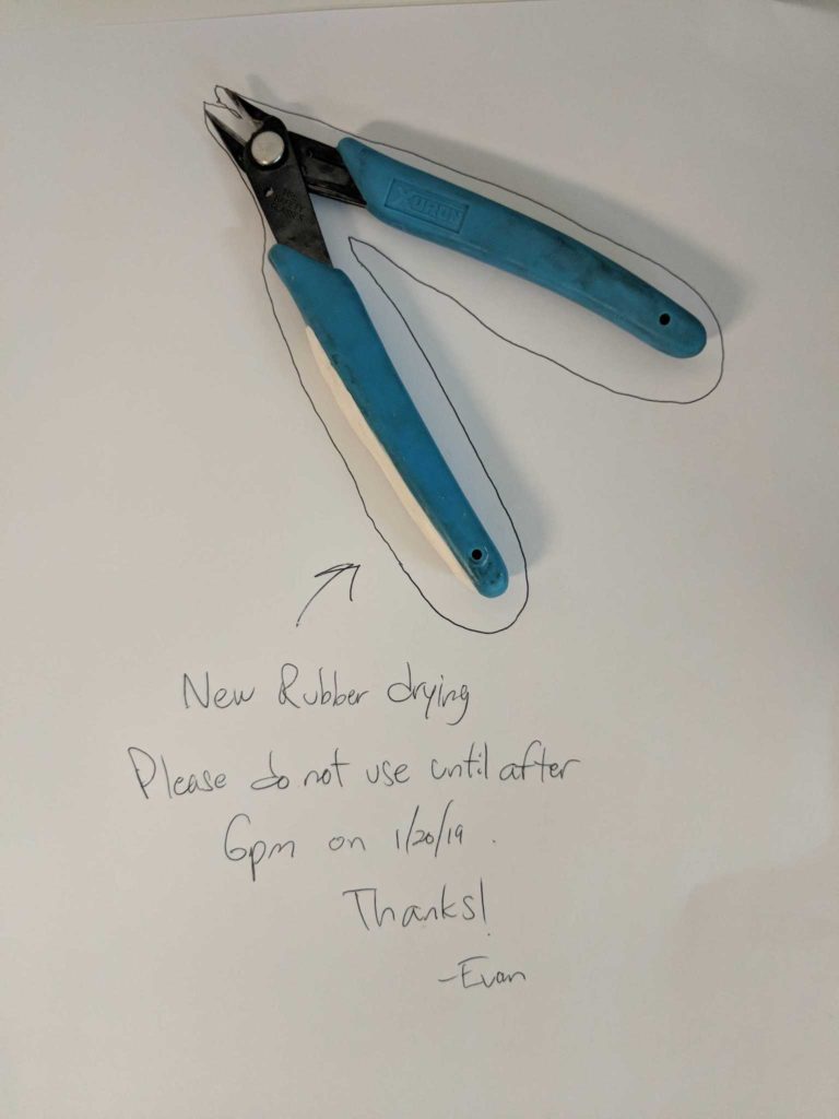
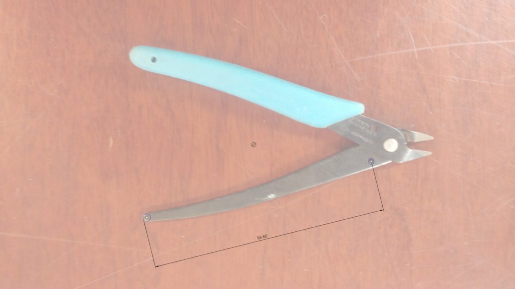
To model it, I took a photo; then used Fusion’s ‘attached canvas’ feature. The easy way to use this feature is to simply import the image, without entering any dimensions at all. Then, right click the attached-canvas object in the browser and select calibrate. Fusion will prompt you to select two points. I’ve chosen the little hole near the joint and the end of the tang, which measures 98.6mm
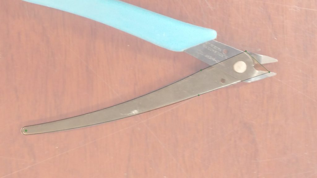
Now we can make a sketch of the profile. I fitted arcs to the shape as near as I can. I find this easier than using splines when the shape allows for it. I used the ‘Fix’ tool instead of dimensions, since the scaled photo is what really defines the size here. I did not bother modeling the business end of the tool.
Next I extruded this profile to a 2mm thickness.
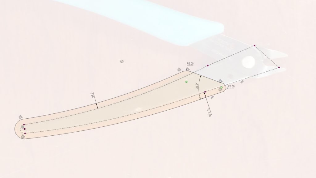
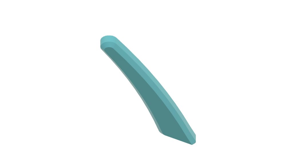
This was done in a component called tang. Next I created a new component called grip and sketched the outer profile. I projected the tang outline first; then offset the lower and sketched the upper end to eyeball-match the existing grip.
This was extruded ‘downward’ to create the basic shape of the lower half of the grip.
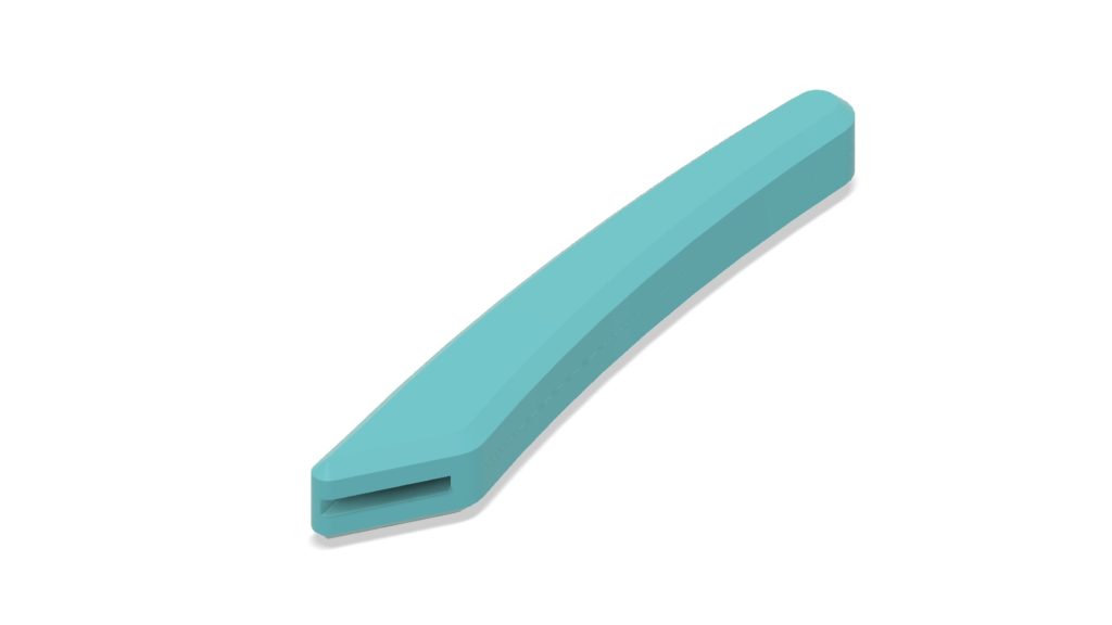
Next, I sketched a profile and cut away a depression for the inner part. This profile was offset from the tang outline very slightly (0.2mm) to allow for a reasonable fit. In this case, I may have to adjust the dimensions for fit a few times anyway, so this step could probably be omitted. Still, I think it’s good practice to explicitly design appropriate fit clearance for mating parts.
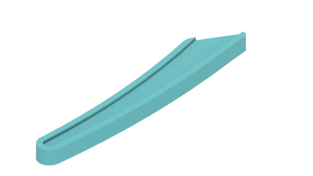
A chamfer on the bottom completes the grip. It’s not an exact match but it’s close enough.
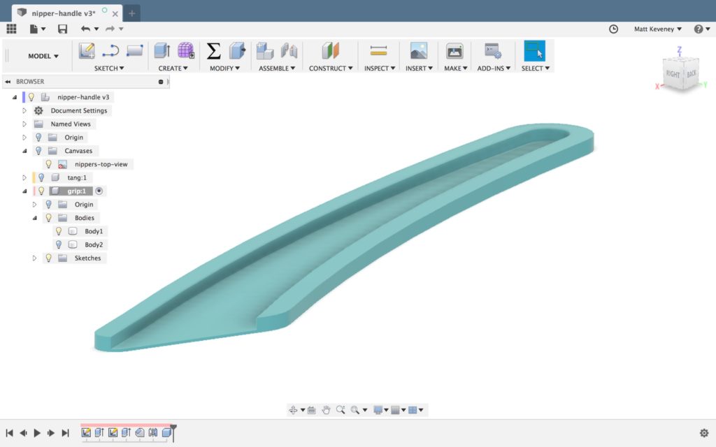
Finally, I mirror the body to make the top half of the grip. I’ll print in two pieces and glue them together to avoid using support material.
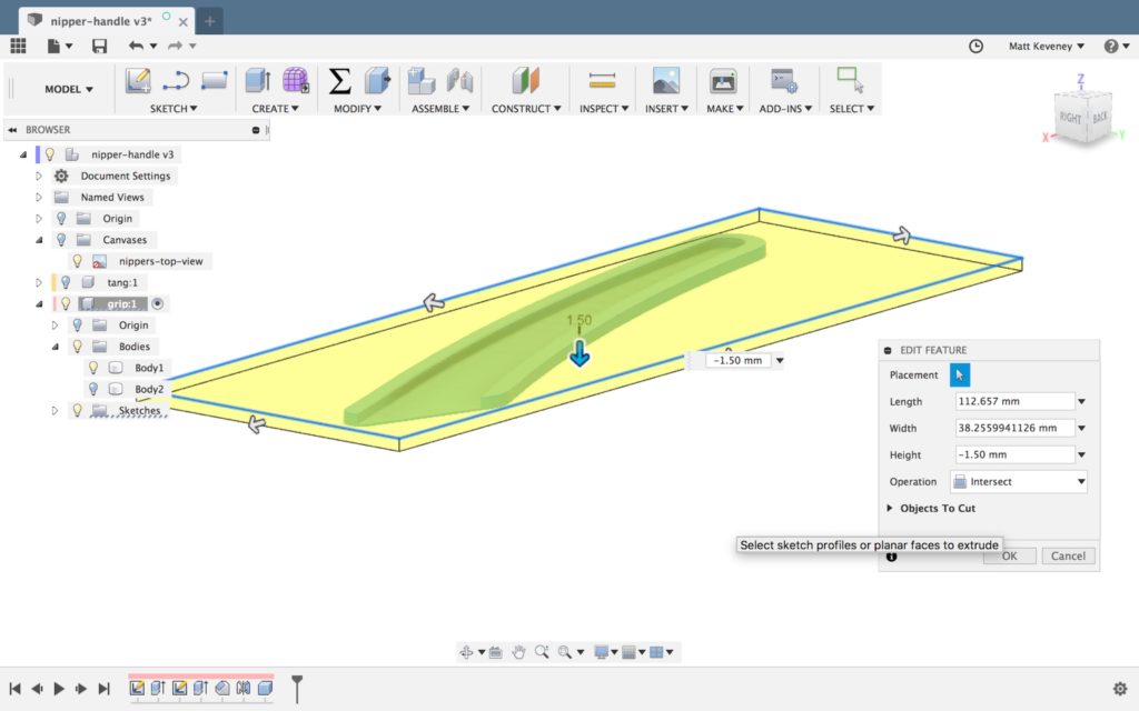
When I don’t know for sure that I have the size of something right, I often print an ‘abbreviated’ version to test the fit. This part’s small enough that I probably don’t need to, but just to illustrate the step, here’s what I do. Use the box tool, with the intersect operation. Drag the box until it surrounds the area of interest. Precise dimensions are not necessary here; we’re just isolating the feature to be tested.
In this case, I’ve simply shaved off the bottom few millimeters. I can cancel the print after just a few layers and see how well it fits the handle.
Once I’m done testing, I can simply disable (or delete) the box feature in the history timeline.
Let’s print it and see what we’ve got!
Hm… not quite. The inner curve seems right, but the outer is too tight. I’ll tweak the first sketch and try again.
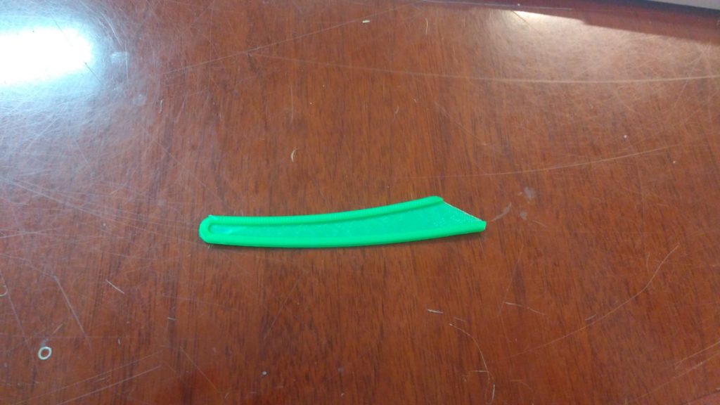
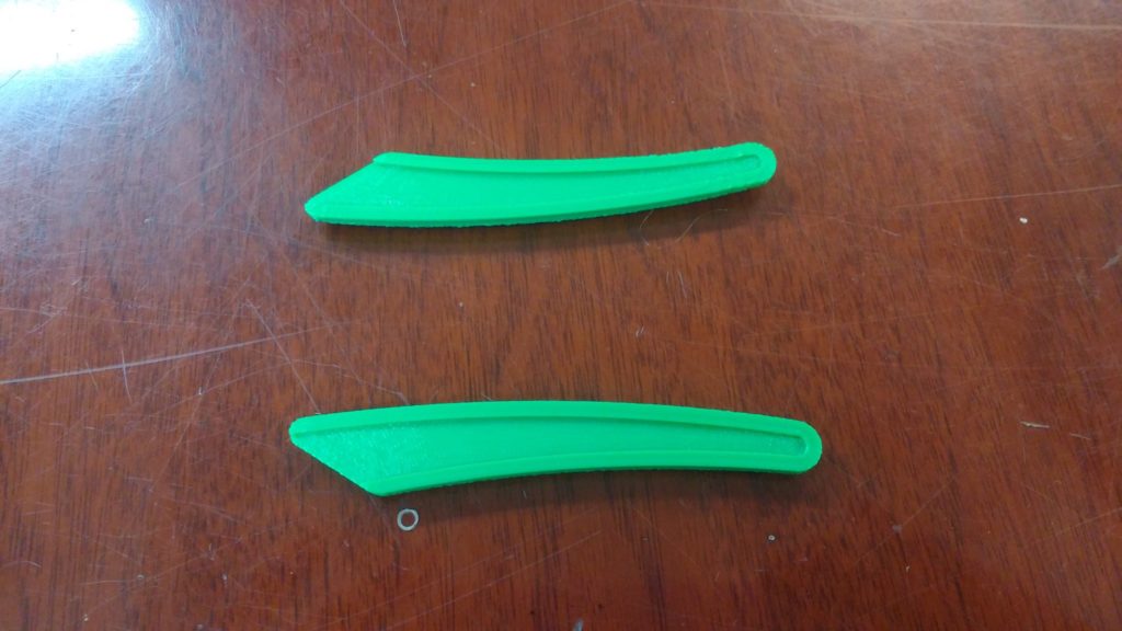
This one’s still not perfect, but I think it’s close enough. Here are the complete parts, fresh off the printer.
The fit is okay but there are a few minor issues: The parts warped very slightly when printed, and the cavity for the tang was just a hair too shallow.
A bit of glue and clamping would probably have solved the problem but I had to knock off for the day anyway, and took a bit of time the next day to reprint at my own shop. I even had some blue filament that’s a closer match to the original grip.
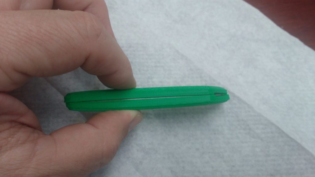
Here it is, glued and clamped up. I gave the mating faces a light sanding to help the glue stick better. I used thick, gel-style cyanoacrylate glue, which gives a few seconds to line things up before it grabs. It seems to work very well with PLA.
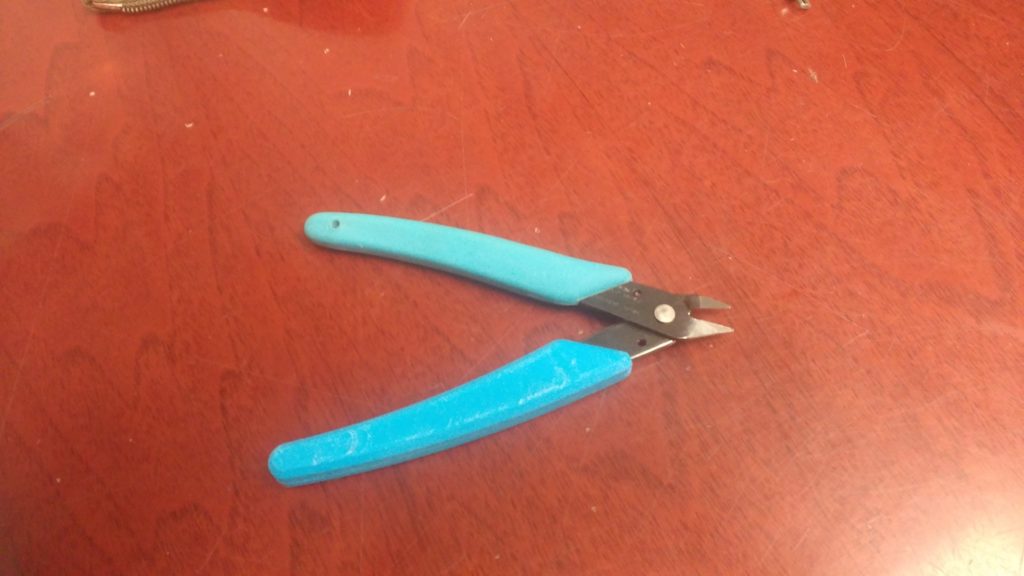
And here’s the result. Let’s hope it lasts longer than the original!
But wait… Has this all been worth it?
Well, probably not. I found brand-new nippers from a US vendor for $3.09 on eBay. They’re even cheaper if you order directly from the Far East.
Oh well. I think the techniques are worthwhile to know. The main thing is that it made for a good blog post!
I know what you’re thinking. I’m sure you think this all the time.
You’re thinking:
‘Gosh, I get so much out of Ace Monster Toys; I’d really love to give just a little back! After all, the membership agreement says I’m supposed to do one small thing a month, and one big thing a year. Boy, I don’t know though… what could a simple soul like me really accomplish?’
Then, you might think:
‘But, golly, I really don’t want to bother the officers or stewards with questions like this. They’re so busy already, I’d just be getting in their way.’
Have no fear! We’re never too busy to put you to work.
Here are a few ideas I’ve come up with in 3D printing. I’m sure any of the stewards will have other ideas if these don’t appeal. The first three could be done while waiting for your next long print to finish!
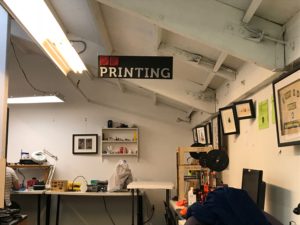
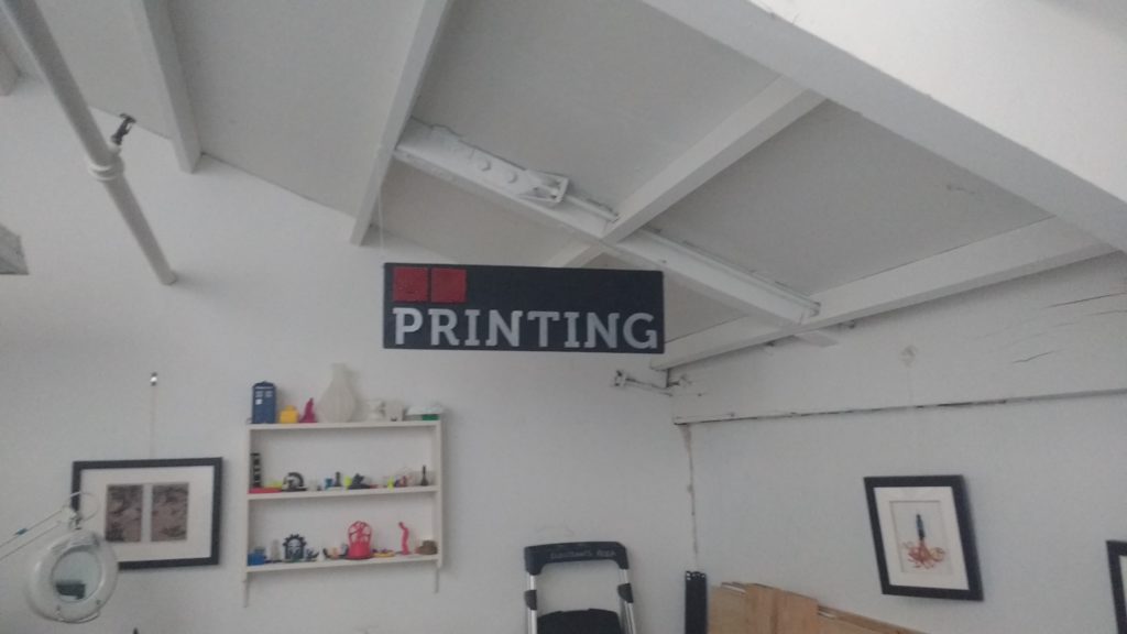
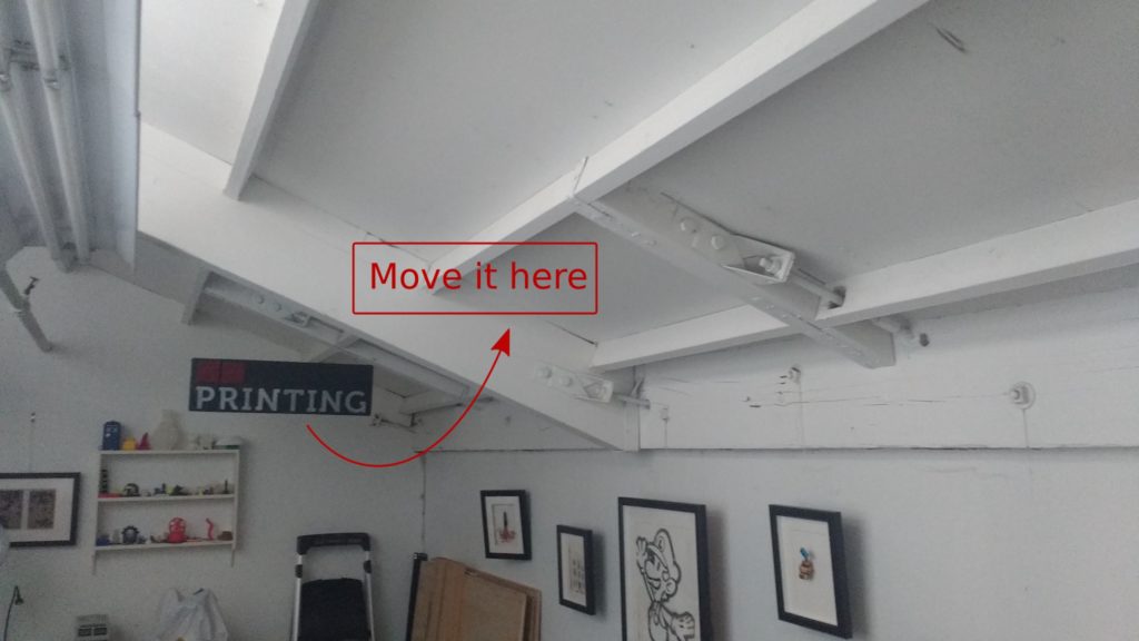
Move the sign!
Now that we’ve stretched out along the west all, the sign is kind-of lost back there. Unscrew it and re-hang it. I’m thinking right over the Type-A printer would be a good place.
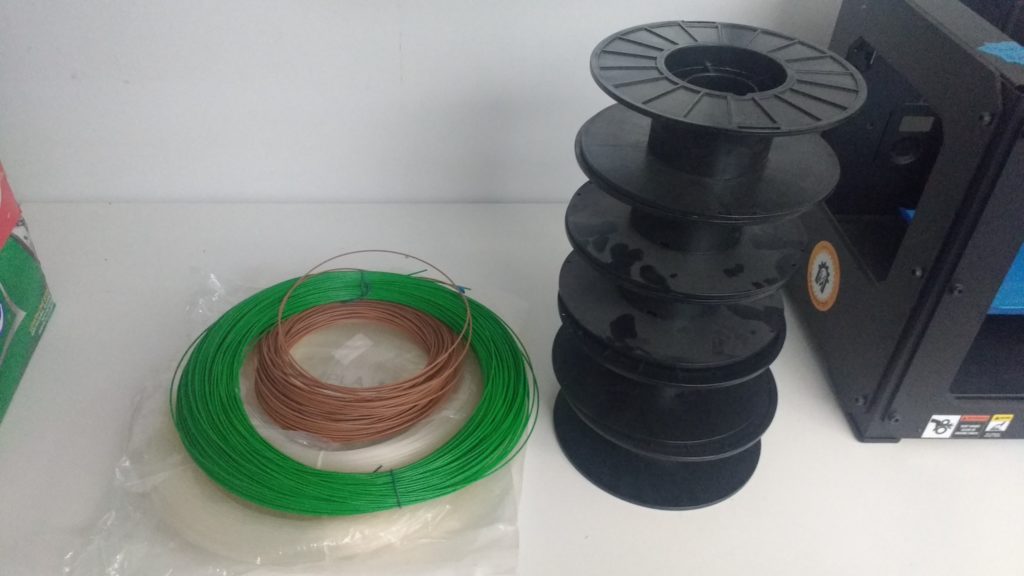
Wind some filament!
We have four loose spools of filament: two of natural PLA, one ‘wood fiber’, and another green ABS. Wind them onto spools so we can use them! You could do it by hand if you’re really bored, but I’d rig up a temporary axle with some clamps and sticks borrowed from the workshop. Something to do while waiting for your next long print!
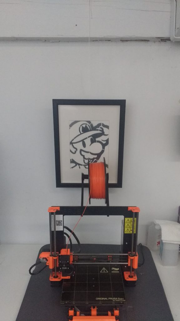
Re-Hang Mario!
The Mario artwork is now hidden behind the Prusa. Move it up a few inches! That’ll require a hot glue gun and a bit of knot tying.
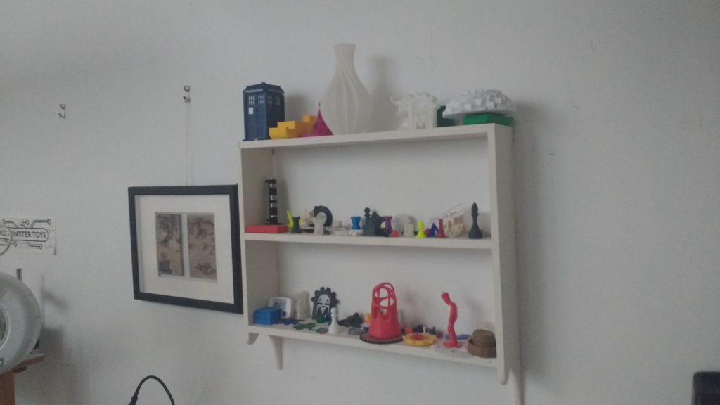
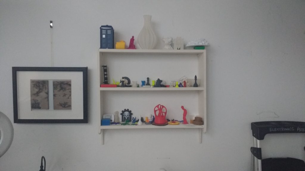
Make a new shelf!
Last year, Devon was good enough to build us this cool little shelf to hold 3D printing samples. Since then we moved upstairs and then rearranged again. But, now there’s no place to hang the shelf. (We’re not allowed to hang it on the nearby concrete wall.)
Instead, I’m thinking we ought to have a free-standing bookshelf-like-thing about the same size, to live atop the filament cabinet. Please talk to me before embarking on this one, so I know we’re on the same page! This would be a great candidate for your ‘one big thing’ for the year.
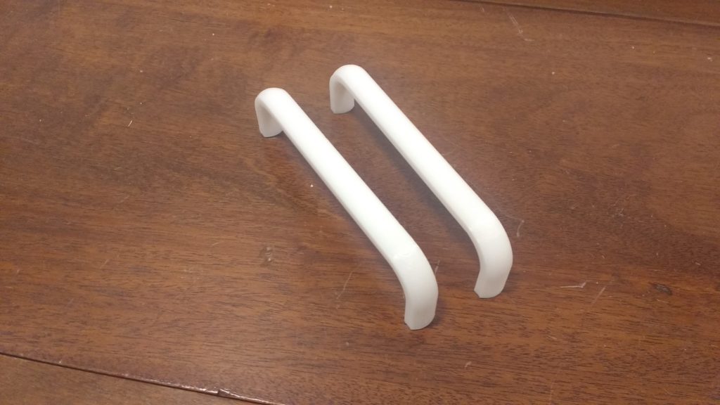
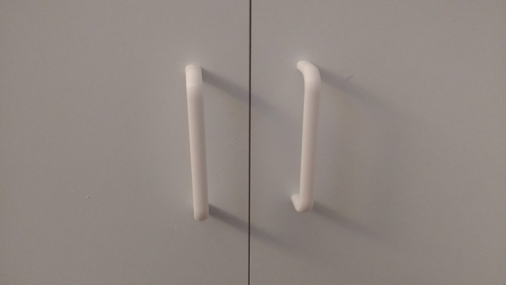
My folks just moved here from out-of-state. Naturally a few things got broken in transit, including the cabinet door handles for a simple storage unit.
There was nothing appropriate in the right size at the local hardware stores. These have holes 5″ apart, which seems to be larger than average.
This is a great example of a simple and practical use of 3D printing. It didn’t take long to design or print, and looks great!
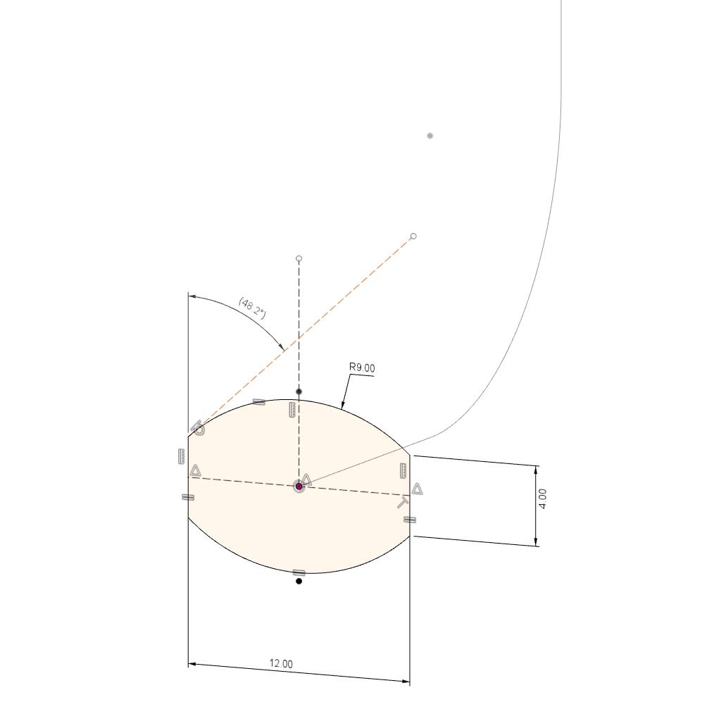
The originals were of circular section, which can be difficult to print. I designed a slightly different section that would print on its side without any support material. Note the use of a ‘driven’ dimension, just to manually ensure that the angle with the build surface will be at least 45°.
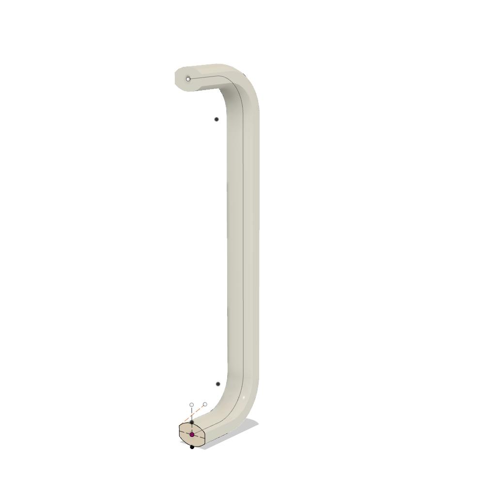
The body is generated with a single sweep operation.
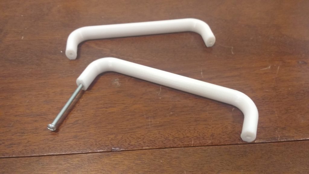
The threads were too fine to print, so I modeled holes and tapped them afterward. Tapping plastic is a tedious process. You must withdraw the tap and clear the chips about every 3mm. While I’m always skeptical of plastic threads, these seem to be holding up quite well so far.
Further proof that 3D printing is not just for cereal box toys anymore!
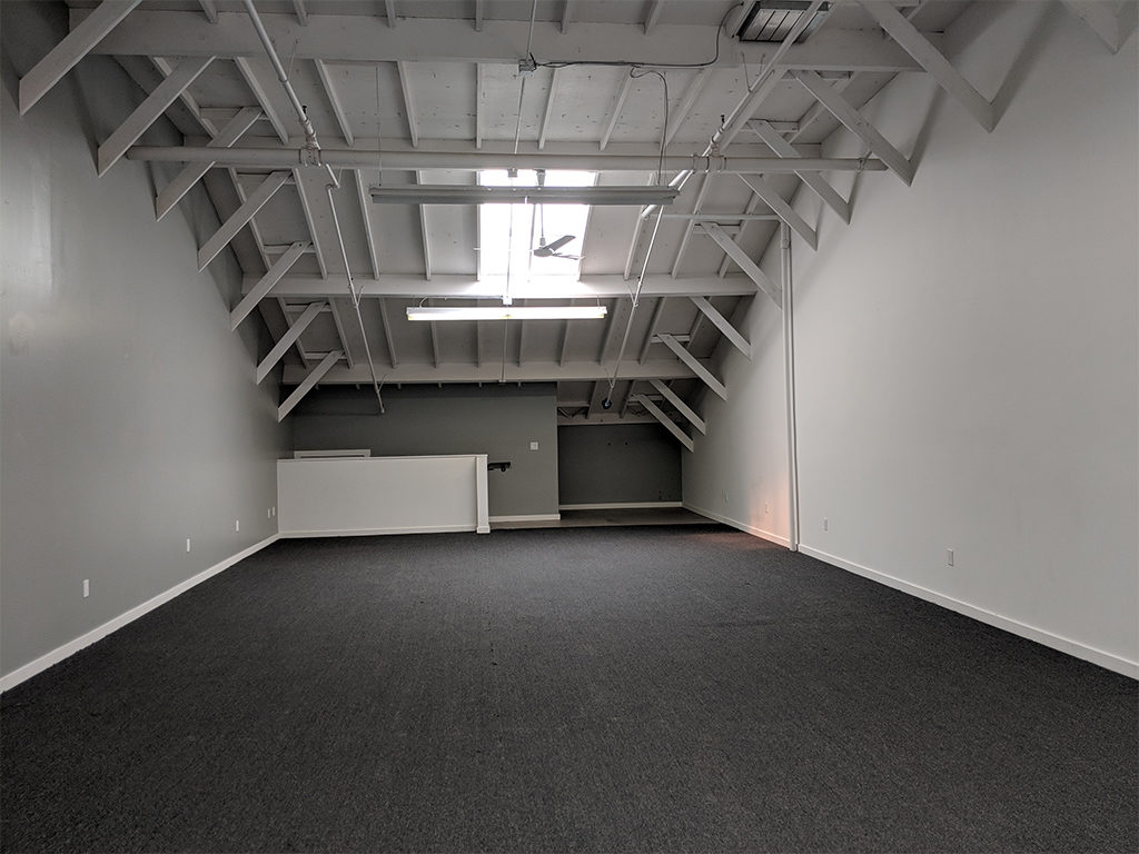
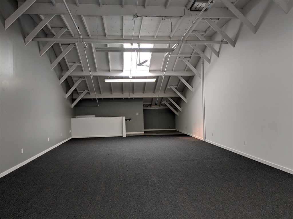
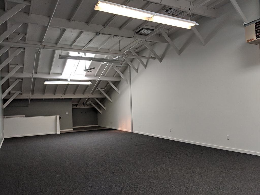
This month AMT turns 8 years old and we are growing! We have rented an additional 1200sqft suite in the building. We have a Work Party Weekend planned June 1-3 to upgrade and reconfigure all of AMT. All the key areas at AMT are getting an upgrade :
CoWorking and Classroom are moving in to the new suite. Rad wifi, chill space away from the big machines, and core office amenities are planned for CoWorking. The new Classroom will be reconfigurable and have double the capacity.
Textiles is moving upstairs into the light. The room will now be a clean fabrication hub with Electronics and 3D Printing both expanding into the space made available. Photo printing may or may not stay upstairs — plans are still forming up.
Metal working, bike parking, and new storage including the old lockers will be moving into the old classroom. But before they move in the room is getting a face lift by returning to the cement floors and the walls will get a new coat of paint.
The CNC room and workshop will then be reconfigured to take advantage of the space Metal vacated. We aren’t sure what that is going to look like beyond more workspace and possibly affordable storage for larger short term projects.
The other thing that happened in May is after 8 years our rent finally went up. It is still affordable enough that we get to expand. Expansion also means increasing membership volume to cover the new rents and to take advantage of all the upgrades. We are looking to add another 30 members by winter. Our total capacity before we hit the cap will be 200 members. We feel that offering more classes and the best bargain in co-working will allow us to do this. Please help get the word out!
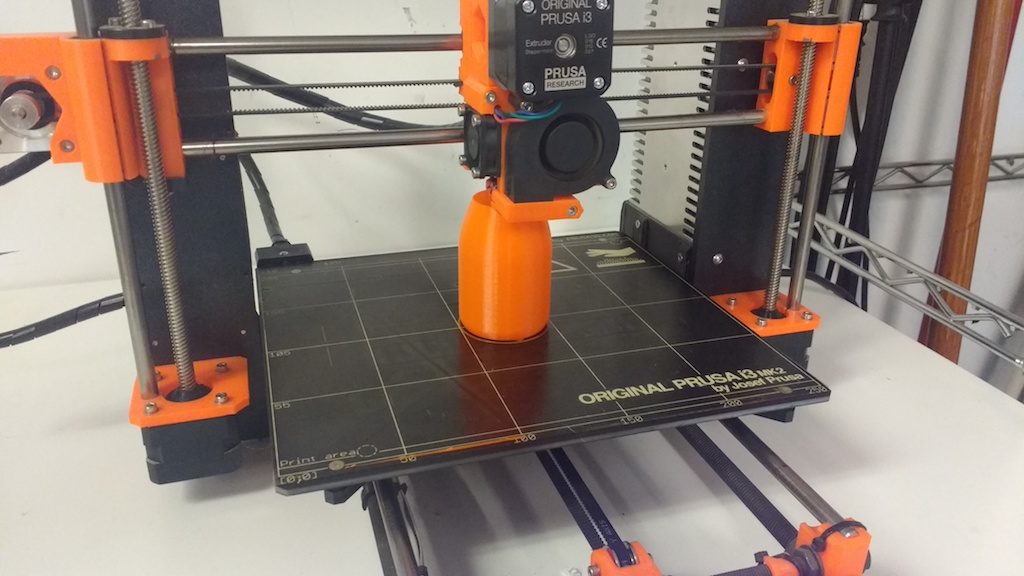
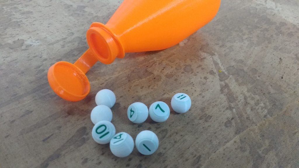
In the last article, I shared a few photos of the numbered ‘billiard peas’ I recently made. Traditionally, these are selected from a pea bottle. This was a great opportunity to try the sample PETG material as well as the ‘spiral vase’ mode available in Slic3r.
When printing anything with a single-thickness wall, there is always a small flaw where the printer advances to the next layer. By default this point will land at nearly the same XY position, yielding an unsightly ‘scar’ running up the side of the piece. This scar is also a weak point of the print.
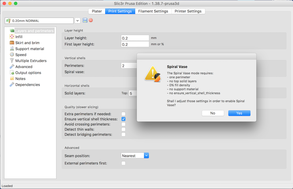
For this reason, most slicers feature a spiral mode. The printer moves continuously around the perimeter, advancing very slowly and evenly in the Z direction. This gives a superb, continuous surface finish.
When activating this mode, Slic3r PE automatically sets related settings accordingly; No top layer is allowed, perimeter thickness must be just one filament wide, etc. You can still control the with somewhat by adjusting the extrusion width in the ‘Advanced’ menu. I changed perimeters from .45 to .6 to get a slightly stronger bottle.
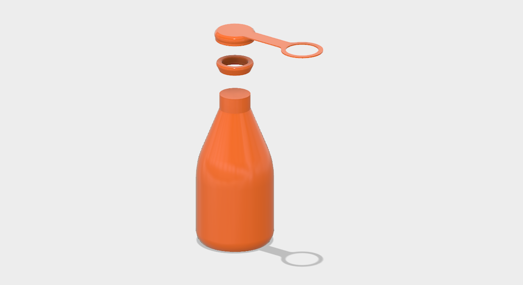
The model should be defined as a solid; otherwise Slic3r will try (and fail) to create both inside and outside surfaces. Model the outside dimensions only.
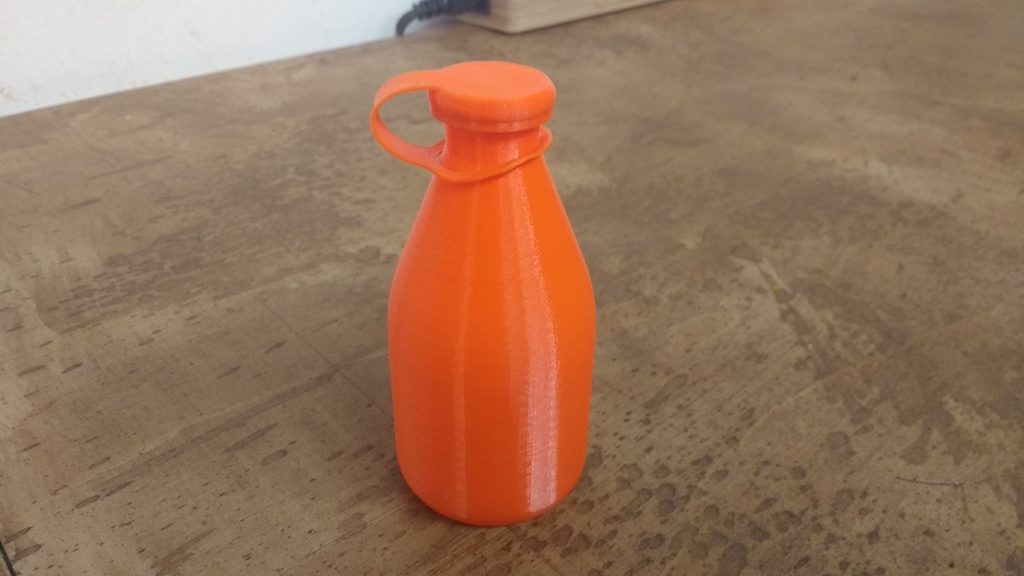
Since I wanted a stronger lip for my bottle, I designed a separate piece to be glued on later. I also made a snap-on cap, with a retaining ring, just to see how well this works with PETG.
I’m happy to say it worked perfectly on the first try. The PETG material is easy to work with on our Prusa, and noticeably more flexible than PLA when printing such a thin section.


 Ted is a long-time friend of Ace Executive Director Rachel Crafty, but Ted’s story begins before Rachel was in that role. Ted works in a laboratory, and throughout his working process, he sometimes finds that he needs to make custom-built parts in order to fulfill certain jobs. He normally would make these parts out of wood, (Ted is a master woodworker) but one day the job required a small beaker holder that was too fine to make with wood. Hearing about Ace’s 3D printing workspace, Ted decided that he should learn some basic skills in 3D printing so that he could handle situations like these. He admits the process wasn’t very smooth, but in the end, he had a working product, and that experience made Ted very interested in 3D printing as a whole.