Author: Purge Users Ace Makerspace

Learn Something New with 3D Printing

Last night, I went to my first 3D Printing 101 class at AMT.

3d-printing-101

It took me about a month to finally let go of all my excuses and commit to this intro class, but I’m glad I did. As a new member, I was sold on how much I could gain from the facilities and all the new things I could learn… but I knew there would be a HUGE learning curve with learning CAD/CAM design software and I wasn’t sure if I’d be patient enough to stick with it to be honest.

If you’re a new member, and have had the same doubts as I have, don’t fear, there are great people, instructors, and resources here every step of the way. This 3D Printing class was hosted by the amazing Volunstructor (Volunteer Instructor) Matt Keveney, and he definitely knows his stuff.

The class is about 2-hours long with the first half focused on the foundational concepts and printer settings, and the second half on the basics of Fusion 360 and a print project suggested by the class.

For this session, we decided to print out a Chop Stick Rest.

Our concept:

Our model:

It looks simple, but it took about 20 minutes to print out.


Matt even showed us one of the projects he’s been working on.


It’s an Eye Glass Holding Mount!

3D printing has been trending for a while now and I’ve always been fascinated with the creative possibilities, and now I know enough to get started.

After reading through this I hope you’re less intimidated and more inspired. Go out and make something– We are a Makers space after all. 🙂

Don’t forget to look at the calendar for all the new upcoming events:

Ace Monster Toys

Emeryville, CA
4,079 Makers

Ace Monster Toys is a Oakland based hackerspace. Visit our website to learn all about us.Where people make things and help others make things in a 24/7 shared workspace.

Next Meetup

Textile Tuesday

Tuesday, Jun 25, 2019, 7:00 PM
2 Attending

Check out this Meetup Group →


Adventures on the Axis of X and Y

The following is the story of one dedicated AMT members adventures in caring for our beloved hacked CNC Router.

When I previously measured the steps on the x-axis, I found a big step difference between the forward and the backward motion. I decided to remove the x-axis to see if there were any mechanical reason which might affect this. At the same time, I removed the z-axis to see if there might be a mechanical reason for the occasional dropping of the z-axis.

z-axis

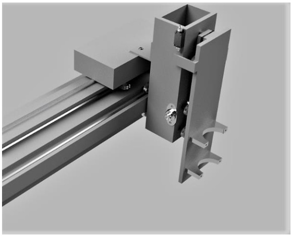
I removed both z-axes from the CNC and checked the Porter-Cable axis for wear. In addition, I checked to see if there was any slippage between shafts and timing gears, as well as between the shaft and the coupler. (This was a suggestion from @drshiny.) To me, the z-axis looks in a good condition. I identified two issues, one was the timing belt and the other was that the guide wheels were not running tightly on the Guide rails.

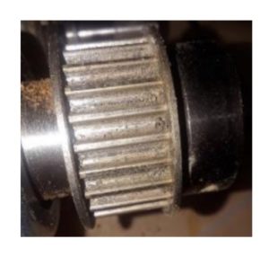
The teeth of the timing gear were clogged with debris which looked like it had come from the timing belt. The only picture I have was taken after cleaning, but before doing that, I found a surprising amount of black stuff which was compacted into the grooves. I swapped the belt with the one from the Perske spindle which I assume has not done the same amount of work.

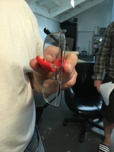
The groove in the bottom of the guide wheels was filled with compacted debris which caused the wheels to not run tightly on the guide rails. The point of the rail sits within the groove of the guide roller. If there is debris within the groove, the guide sits only on the upper face of the guide wheels as shown on the left-hand picture as opposed to the right-hand one(you may need to enlarge the picture to see it).


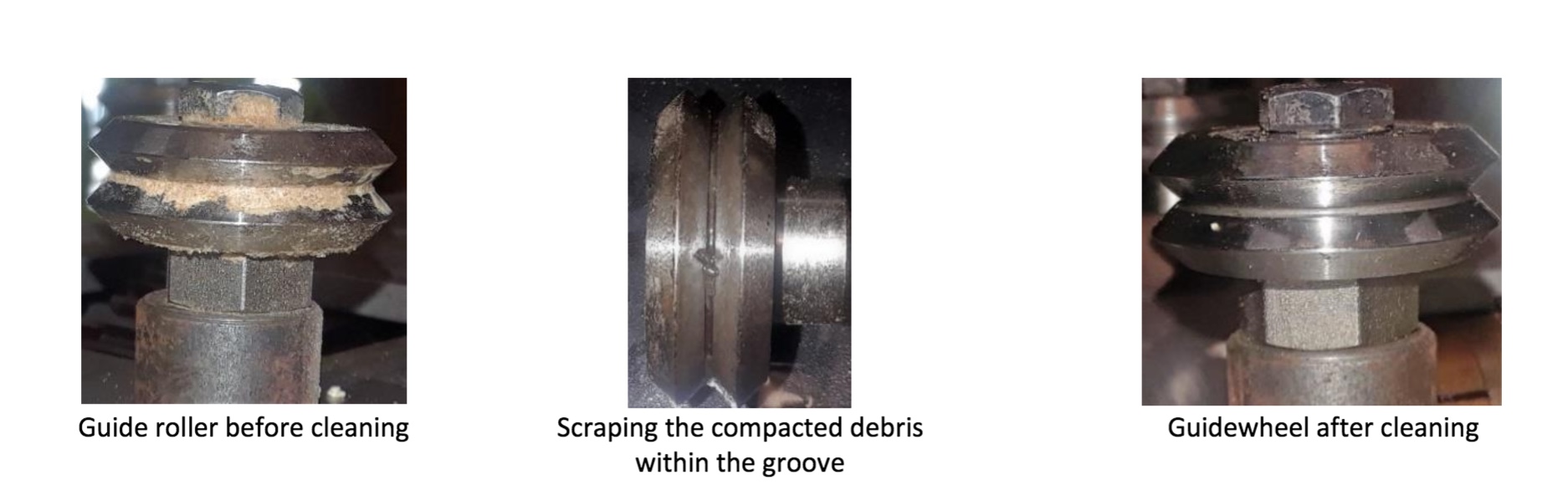
I used WD40 to softened the debris, and then used the edge of a chisel to scrape the stuff away. It was necessary to repeat this process several times for each wheel.

x-axis

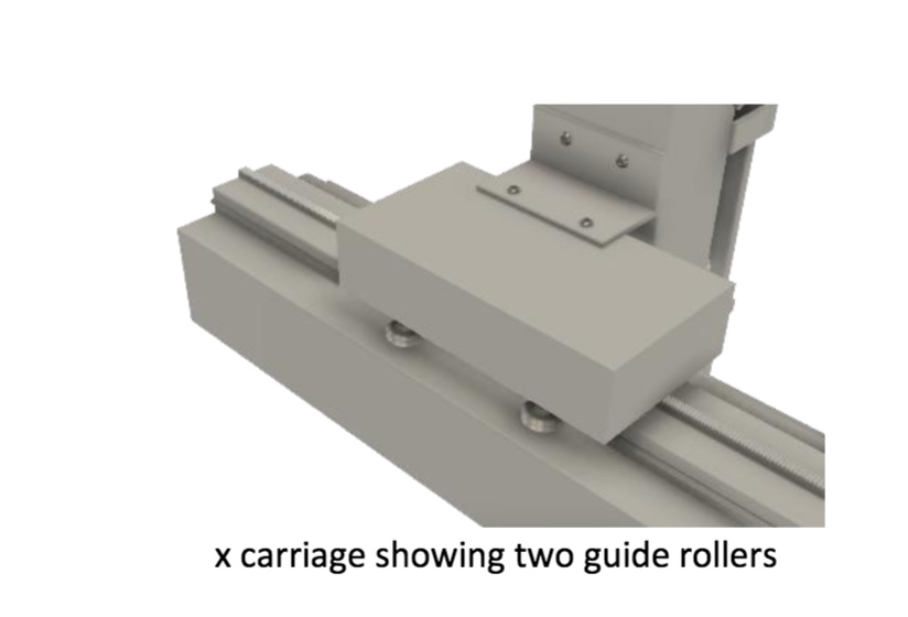
After removing both of the z-axes and the timing belt on the x-axis, I discovered that the x carriage was running only against the back two guide rollers(or wheels), with daylight showing between the front guide roller and guide rails. As before I cleaned and scraped the guide rollers and after tightening the two adjustable back rollers, I tested the smoothness of the carriage by pushing the x-axis forward and backward by hand along the path. At this point, the carriage was running smoothly. When I tested the number of steps forward and backward, I found there was no longer such a big discrepancy, which was the reason I decided to remove the z-and the x-axis in the first place.

y-axis

We know the rack and pinion on the left-hand side has much higher wear than on the right-hand side. I think this is due to the two carriages on the y-axis not running parallel. There are 2 types of guide wheels, fixed and eccentric which means they are adjustable. 2 fixed wheels go on one side and the other 2 go on the other side. I wonder if one of the wheels has been swapped around. That would lead to the carriage being at an angle once tightened. Steve looked at this and also said that the pinion runs at the bottom of the rack and needed to be lifted. It is possible that once the guide wheel has been cleaned and adjusted, it may be enough to lift the rack higher without having to resort to further shimming. This work has not been done yet.

AMT’s Adventures at Maker Faire 2018

The Art Printing Photobooth aka The Edgy Printacular

At the Bay Area Maker Faire 2018, a team of Ace Monster Toys members created a photobooth where participants could take selfies which were then transformed into line art versions and printed, all initiated by pressing one ‘too-big-to-believe’ red button.

Back in March, AMT folks began prepping for Maker Faire 2018, and had an idea: what if you made a machine that could take a selfie and then generate a line art version of the said selfie, that could then be printed out for participants like you and me?! Thus, the Art Printing Photobooth was born! This project was based on the Edgy Cam project by Ray Alderman. AMT created a special slack channel just for Bay Area Maker Faire 2018 #maker-faire-2018. Then members set about figuring out how exactly to make this art-generating-automaton and Rachel (Crafty) campaigned for having a ‘too-big-to-believe’ push button. They would need many maker skills: CNC routing and file design, woodworking, electronics wiring, and someone to art it all up on the physical piece itself. Bob (Damp Rabbit) quickly volunteered to take on the design and CNC cutting, while Ray (whamodyne) started to chip away at the code that would be used to convert photos to line art.


Then the trouble began. By mid-April, our intrepid troubleshooters were running into all sorts of snags – so much so that the original code needed to be thrown out and rewritten from the ground up! To add additional difficulty (and awesomeness!) the team decided to use a Print on Demand(POD) service to allow participants to have their generated art uploaded and available to be printed on mugs, t-shirts, posters, etc. Soon after, Ray wrote up a new digispark code for the big-red-button to actuate the script and convert and print the line art (code given below) using Python3, opencv library, printer library from https://github.com/python-escpos/python-escpos.


Meanwhile, Crafty Rachel and Bernard were configuring the TV mount that would be the selfie-display of the photobooth and Damp Rabbit was busy CNCing and painting up a storm to create the beautiful finished product – The Edgy Printacular! The EP was a hit and won three blue ribbons at Maker Faire 2018. Another happy ending that speaks to what a few creative makers can do when they put their heads together in a place with all the right equipment, Ace Monster Toys <3

Asset Tagging at AMT

Ace Monster Toys has a lot of stuff. We like to keep our stuff organized, so we tag our stuff with labels like this:

How to Look up an Asset

To look up an asset by number or name, you can check the asset list


The assets are listed in number order, and clicking on the Asset Tag (ex. AMT001 for the Big Red Laser) will bring you to the wiki page for that asset. If the asset has been documented correctly, the wiki page will tell you the specifications and dependencies of that asset.


How to Add an Asset Tag

Preprinted asset tags are available on the supplies rack. Please follow the instructions and use them in sequence. You can check which label was used last in the asset list.

You then need to fill out the spreadsheet with the new asset tag under the item number column, give the asset a unique name, give the location of the asset, the URL for the asset’s wiki page (you can copy the URL for the one above and change the tag name), and the value of the asset. Wait, the asset doesn’t have a wiki page so we need to fix this: click on the URL that you put into the spreadsheet, and you will be prompted to create the wiki page (if you are logged in!).

The Wiki page needs to contain the following information:

  • Status: tool integration (Use this code snippet but use the new asset number: {{#amtasset:AMT001}} )
  • Name: Common name of the tool
  • Make/Model: The make and model of the tool from the manufacturer
  • Documentation: (link to documentation, this can be an online manual or on our wiki, whether this page or another is your choice.)
  • Location: (where in the space does it live)
  • Pictures! 
  • Category: (Add relavant category tags for the item you are adding… IT for it stuff, workshop for tools there, etc.)

The Wiki page will become active when the status is set through the Slack channel. To do this, you must send a direct message to @toybot in the format “!asset{asset number}{status}.” For example, if the Big Red Laser is on fire, then you can send a direct message to @toybot saying:

!asset amt001 On Fire!

Messaging toybot can update the status of existing assets (as shown above) as well as setting the status for a new asset.

Happy Tagging!

Aquarium Stand

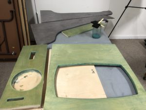
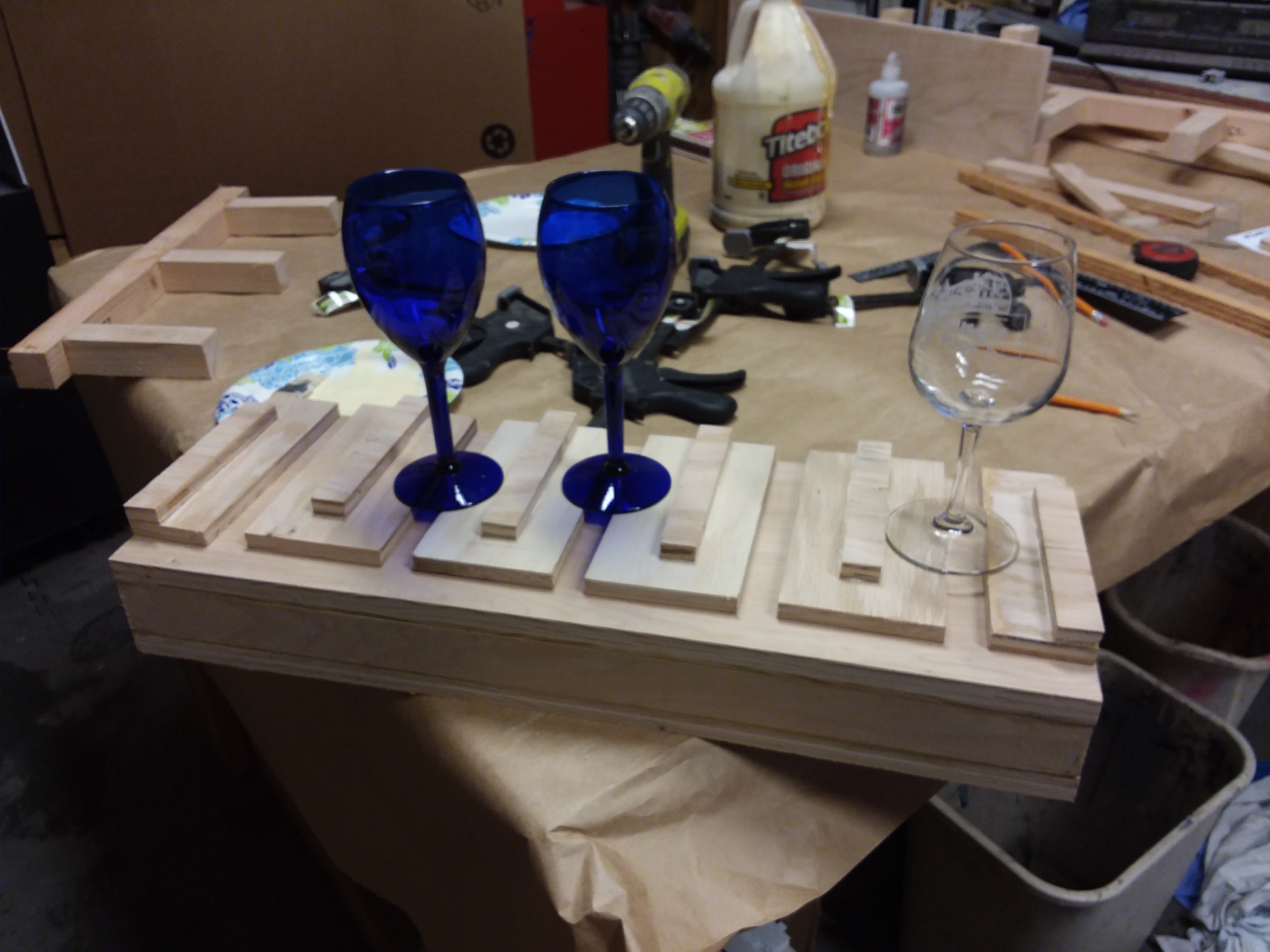
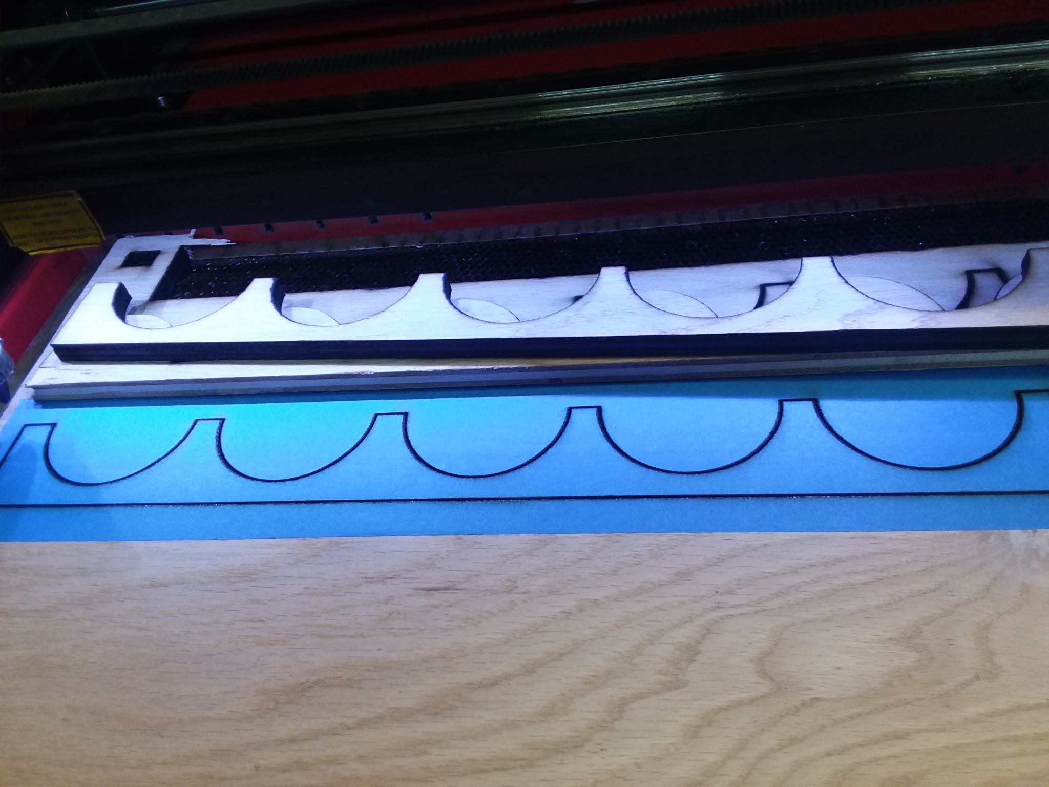
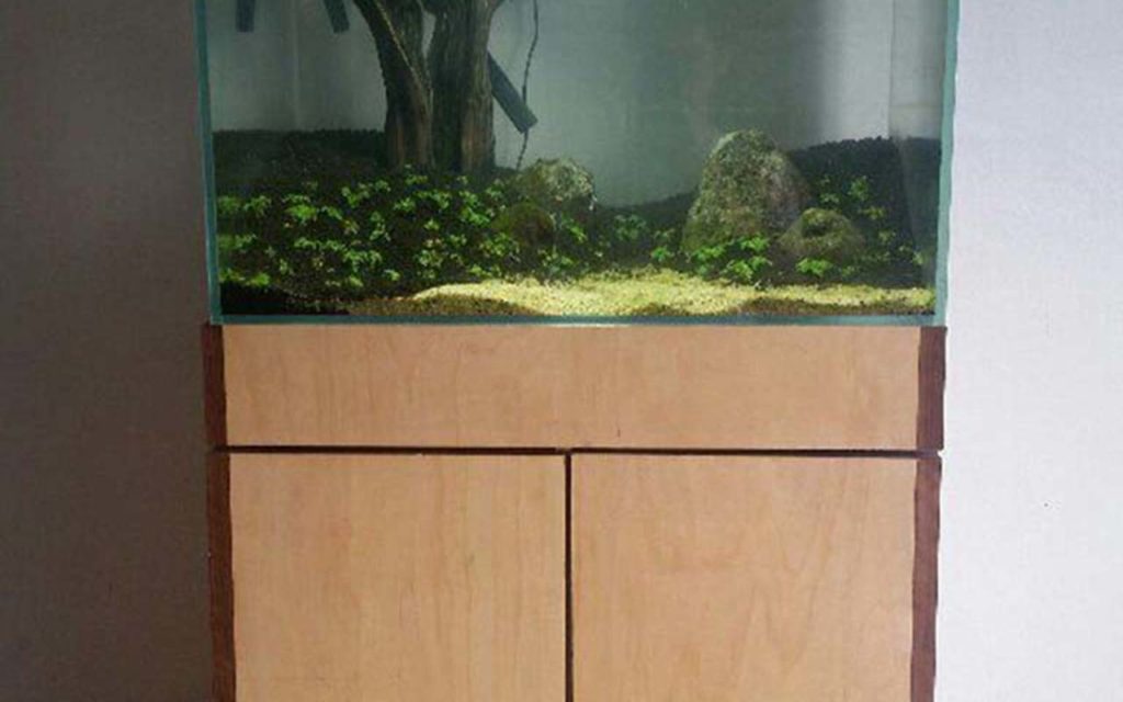
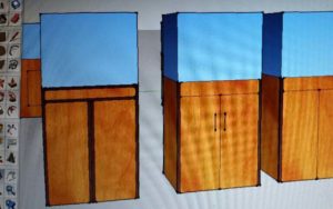
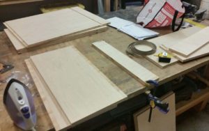
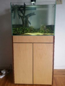
This is an aquarium stand that I built at Ace Monster Toys. It is made of maple 3/4 plywood and walnut edge banding. I used the old craftsman table saw and the ryobi router table to cut and shape the parts. If I had to do it over again I would use the CNC router. It would be far far safer, faster, and the results would be cleaner and more square. I would probably also use strips of 1/8″ walnut instead of the iron-on edge banding, because it would be much more durable and age better.  After designing the piece in sketchup, I made some test pieces to practice edge banding on. The idea is to use the edge banding to hide the screws and the ugly edges of the plywood.  It was a challenge to cut up the 4×8 sheet of plywood with a handheld power saw. A panel saw would have been better.  After getting the pieces small enough to fit in my car, I took them to AMT and cut them to size on the table saw. The problem was that, even with my own brand new blade, the saw would not cut perfectly square, and the measurements on the fence were not accurate. It was very frustrating and the results were not perfect.  I used the router table to cut dadoes and rabbets where the walnut strips would go. After assembling the box, I used an iron to iron on the walnut edge banding, which I trimmed with a razor.  At this point I took the stand home for finishing, and added some wheels. The stand contains my canister filter and CO2 tank. I am very happy with the result, but if I had to do it over, I would use the CNC.

Quadcopter assembled

The Pig Hawk Quadcopter

Quadcopters are really fun, and I wanted to build one for a long time. My main intent was to take pictures and shoot videos from a new angle. Also, this has to be fun to fly!


Team work

Quadcopter teamwork

I was working on this project with a few friends, all of us were absolute beginners when it comes to quadcopters. Since the construction can be split into subtasks it was easy to keep everyone busy, between soldering cables, tweaking the 3D printing settings, or configuring the flight controller. Team work is fun, especially when you spend several hours focused on the same project. Everybody learned something along the way.


Leveraging 3D printing

Quadcopter pieces

Because we wanted to learn about how quadcopters work, we choose to build our own instead of buying one ready to fly. It’s easy to find some sample designs on Thingiverse, for example. We choose to start with the crossfire 2 and customize it a bit to better fit our parts, usage, and to cope with our really poor pilots skills (because crashing means re-printing parts.. And we crash A LOT! :)).


Working on the assembly

Quadcopter assembled

The crossfire 2 comes with a very detailed instruction guide. For most parts you just need to follow the guides, and some parts are specific to the components you choose. We picked the PixHawk flight controller for example (of which the project’s codename is a pun). Overall it was rather easy to get everything assembled. Here you can see the quadcopter with half of the body assembled, the four arms, and the ESCs (Electronic Speed Controllers).


Sample shot

Quadcopter aerial picture

After several weeks of hard work, long hours reading documentation and tweaking the settings, it was time for the inaugural flight. Of course, we crashed it a few times in the process of learning how to fly the thing correctly. But the feeling we got when we were able to make it do almost what we wanted was worth the effort. We hooked up a GoPro on it, and went flying at Cesar Chavez park for a sunset. The view was gorgeous.

AMT 360º How to use the New Cyclone

We have a new dust collection system!

Our previous system (which used to live in the closet) has been replaced and we now have a cyclone dust collector.
The cyclone lives in the metal shop and is hooked up to the ducts in the workshop.

To turn it on, currently you need to plug it into its extension cord. Look for the blue stickers on the right side of the cyclone:


We are interested in your feedback regarding this new system.
You can use our equipment feedback tracking with the asset tag AMT140 to report issues.
Ping us ( @fitzhugh or @pierre ) on slack in the #workshop channel if you have questions about this system!