It all started when Pixie’s college friend asked her to knit him a glamourous rainbow shawl for his wedding! They selected a pattern to serve as a starting point, planned the color story, did a little math to figure out how much yarn it would take, and found a dyer (Pook Yarns) to create a custom gradient. Then it was time to start knitting.
On 11/19/22 she officially cast on–a technique for creating the first row of stitches on the needle…
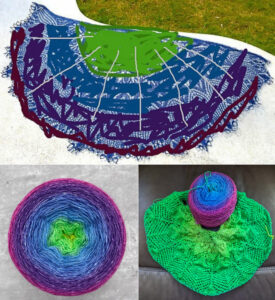
Top: Preliminary sketch of the color scheme. Pixie told her friend “you can be as much of a bridezilla as you want” and received a lengthy list of hex codes in return (html color codes). Bottom left: apx.1000 meters of hand-dyed yarn from Pook Yarns. Image from Pook Yarns. Bottom Right: Pixie improvised a little as she knit to extend the pattern.
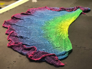
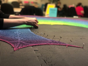
…6 months later she finished the last stitch and the shawl was ready for blocking!
See that curly edge? Once it’s blocked it will look totally different.
Blocking describes a finishing process used by knitters and crocheters to even out their stitches and set the shape and size for their pieces. It involves wetting the fabric, stretching it until it’s just right, and allowing it to set as it dries.
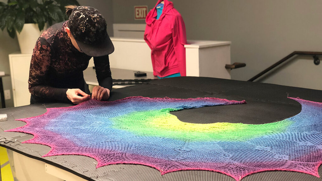
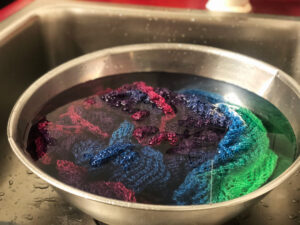
Pixie soaked the shawl and carefully wrung out the water before the next step. Tip: Use lukewarm water for blocking.Pixie used a foam mat and T-pins to hold the shawl in place. Tip: Insert pins at a slight angle for stability.
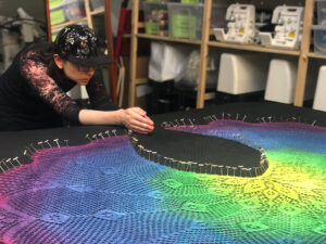
Since Pixie improvised a little to extend the pattern as she knit, she wasn’t entirely sure what the final shape would look like. Though she started pinning the outer edge into sharp points, she decided to re-pin it with a scalloped edge to better showcase the lace details. She also wasn’t sure what shape the neckline would take and re-pinned it several times to get it just right.
Pixie checks to make sure the shawl is stretched evenly. Each minor adjustment means removing and re-inserting pins until it’s just right. Tip: Allow extra ease when you cast off–technique for finishing the last row–so that the yarn doesn’t snap as you block.
Stretching is an art. You have to fiddle with it to see what happens -Pixie
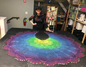
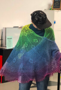
Pixie posing with her blocked shawl after almost 2 hours of pinning, tweaking the shape, and carefully stretching the delicate lace.
Once she finished blocking she allowed it to dry overnight and then removed the pins.
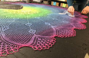
The moment of truth! Check out that scalloped edge!Pixie tries on her finished piece!
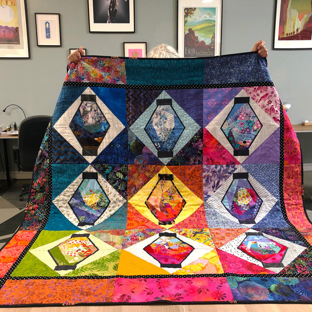
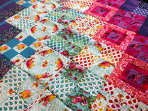
Terry showing off her favorite “Lantern Quilt” for a “Reddit-style quilt photo.”
Terry’s been sewing most of her life, but until last spring (2022) had never tried quilting. Now, one year later, she’s made 13 quilt tops and counting! When you ask what prompted her to start, she isn’t exactly sure apart from her “fabric hoarding” tendencies.
I’ve started thinking about my life as a maker life. Making things has always been my favorite part of every job I’ve ever had.
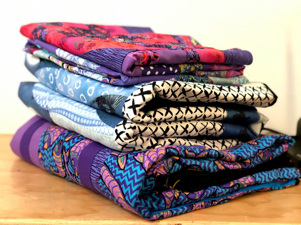
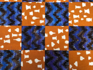
The inspiration for her quilts tends to come from the fabrics she’s collected over the years and her experiences both past and present. She made her first quilt at Ace from a stash of batik and paisley shirts she no longer wears but couldn’t bear to part with.
This block from Terry’s first quilt represents her past as a ceramic sculptor and features her “signature fabric” with a vessel motif.
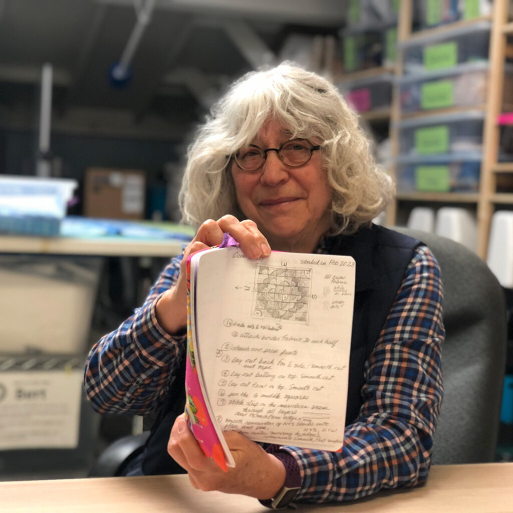
She uses a special notebook to sketch and plan the layout letting the basic shapes in the fabric dictate what “kind of quilt they want to be.”
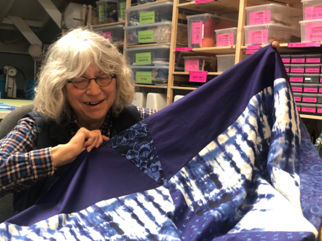
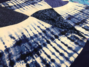
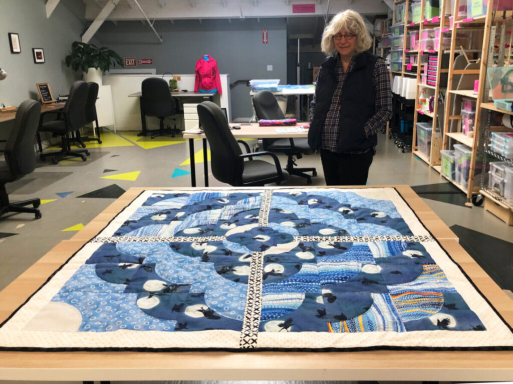
Terry showing her preliminary sketch for her “Angry Birds” crow quilt.Terry talks about how the shape of this tie-dye skirt inspired the curved pattern for her quilt.You can really see the how the skirt shape and fabric influenced the design for this quilt top.
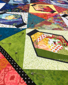
While she really enjoys the process of making quilt tops, she tends to procrastinate on assembly admitting to a closet full of UFOs (unfinished objects).
It took Terry two tries to get this quilt sandwich pinned.Terry’s “Racoon” quilt top.
What’s Next?
Terry is getting really into playing with embroidery, applique, and geometric shapes. She’s also planning a Scrub Jay quilt inspired by the birds she and her partner hand feed in their neighborhood.
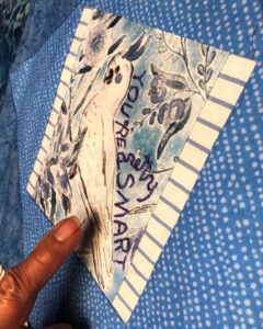
This embroidered quilt square represents Terry’s experience teaching her parakeet to say, “You’re pretty smart.”
Terry’s Tips and Takeaways for New Quilters
“Don’t go it alone.” Find community whether its online, at Ace, or a local quilting guild.
Try a smaller project like quilted oven mitts or throw pillows to learn the mechanics.
It’s helpful to have a space to work away from the distractions at home (like Ace).
Terry examines her finished “Angry Birds” crow quilt.
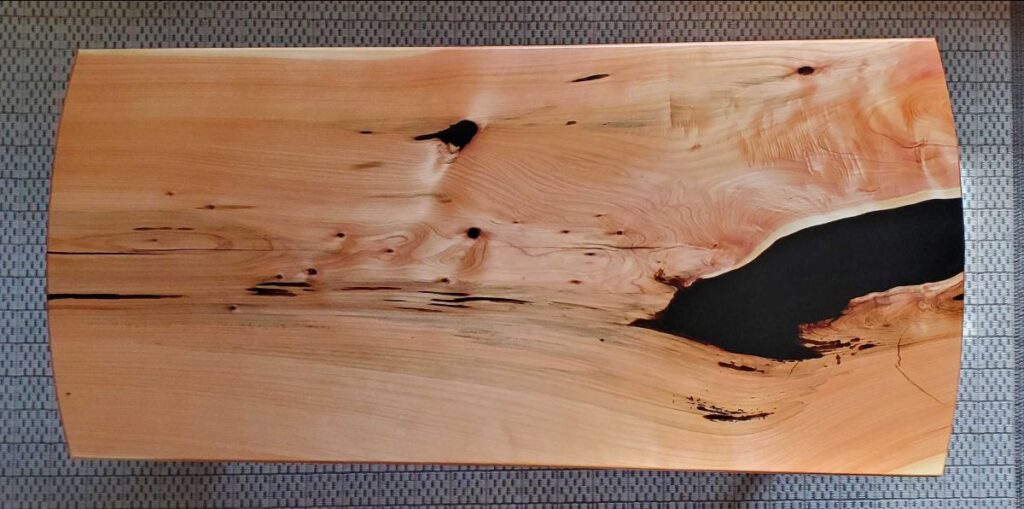
Martin has loads of furniture making experience, but this deep pour resin technique was totally new for him…
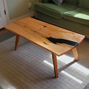
Martin’s finished deep pour resin coffee table
The idea for the project came from Martin’s friends who spotted a sleek resin pour table they liked on Four Eyes Furniture. They asked him if he could make them one so he watched a couple videos and decided to give it a go.
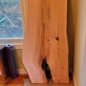
First, he selected a gorgeous slab of kiln dried Monterey Cyprus.
Gorgeous slab of Monterey Cyprus
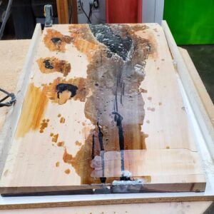
Then he purchased a gallon of Black Epoxy Resin and checked in with the Ace Workshop Community about using Clean Fab for the pour.
Waiting for the first round of epoxy resin to cure.
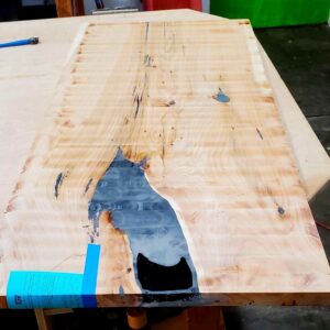
Martin filled the gaps in two rounds; first the top and then the bottom. Each pour took several days to cure before he hand planed it to remove extra resin from the surface.
Martin’s coffee table after hand planing to remove excess resin.
Martin’s tips and takeaways:
Resin costs $$$
It takes time, patience, and a little planning. Each pour takes several days to cure.
After the resin sets, planing the surface by hand is labor intensive. Be prepared to roll up your sleeves.
Monterey Cyprus Wood dust is particularly irritating so well fitting PPE is a must
He’d do it again, but mostly because he has extra resin…
As usual it was way more work than anticipated, but I’m quite pleased with the final result. I had a to build a ridiculous number of jigs and templates for this thing. –Frank
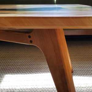
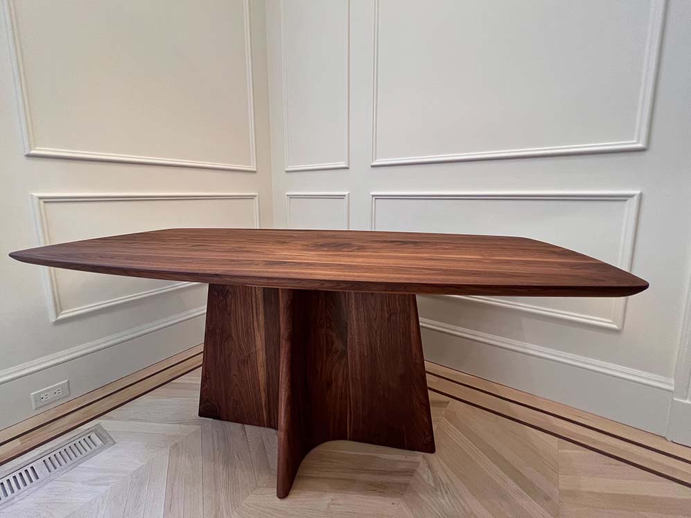
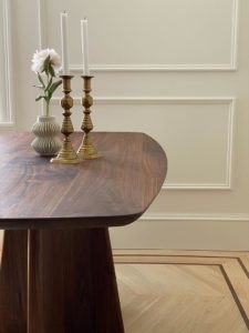
After 4 months of hard work, Frank, a new member, and carpenter completed an absolutely show-stopping dining table in the workshop and posted images of the final piece on the Ace Community Discussion Board.
Prompted by the Ace Community, Frank also provided insight into his process and the many tools he used to design, sketch, render, and build his dream dynamic, curvy table.
I’ve only been woodworking earnest for about the past year. I dabbled with it in college as well but just a bit. Most of what I know has been from the school of YouTube or from talking with people around Ace, and being a mechanical engineer has helped with some aspects.–Frank
Check out some highlights from his build:
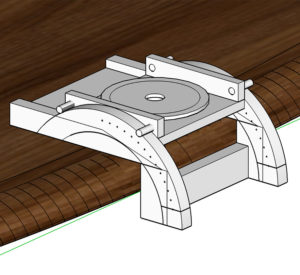
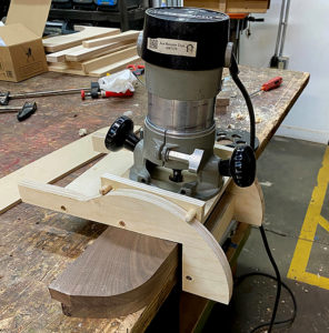
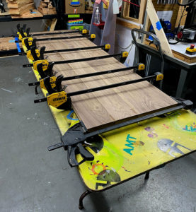
Frank built a “ridiculous” number of custom jigs for shaping the unique curves of his design. See how he takes his idea, renders it, builds it, and tests it below:
Rendered JigTesting the Jig
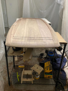
He also put together a super neat glue-up for the top of the table:
Super neat and tidy glue up
He even converted his living room into a stylish workshop and all that between his 10-month-old’s naps!
Frank’s living room converted into a workshop
The project may have been “way more work” than Frank thought it would be but, wow! Hopefully, he’s sending out dinner invites soon!
Hi, my name is Mark. I’ve been a member of ACE for almost 9 years. There’s been three things on my To-Do list gnawing at my psyche for some time:
Learn about Raspberry Pi microprocessors through Internet of Things (IoT) applications.
Get hands-on experience with Artificial Intelligence.
Learn the popular Python programming language.
Why these? Because computers are getting smaller while getting more powerful; Artificial Intelligence (AI) is running on ever smaller computers; and Python is a versatile, beginner-friendly language that’s well-documented and used for both Raspberry Pi (RPi) and AI projects.
I’ve been working in computer vision, a field of AI, for several years in both business development and business operations capacities. While I don’t have a technical background, I strive to understand how the engineering of products & services of my employers works in order to facilitate communication with clients. Throughout my career I’ve asked a lot of engineers a lot of naive questions because I’m curious about how the underlying technologies come together on a fundamental level. I owe a big thanks to those engineers for their patience with me! It was time for me to learn it by doing it on my own.
Computer Vision gives machines the ability to see the world as humans do – Using methods for acquiring, processing, analyzing, and understanding digital images or spatial information.
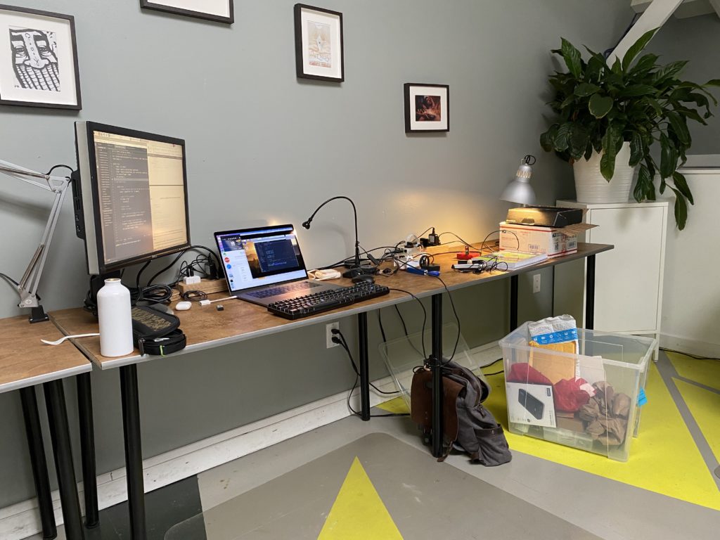
In starting on my learning journey I began a routine of studying at our ACE Makerspace coworking space every week to be around other makers. This helped me maintain focus after the a pandemic induced a work-from-home lifestyle that left me inhibited by a serious brain fog.
My work environment at ACE Coworking
OpenCV (Open Source Computer Vision Library) is a cross-platform library of programming functions mainly aimed at real-time computer vision. AMONG MANY COMPONENTS It includes a machine learning library as a set of functions for statistical classification, regression, and clustering of data.
Fun Fact: Our ACE Makerspace Edgy Cam Photobooth seen at many ACE events uses an ‘Edge Detection’ technique also from the OpenCV Library.
A self-paced Intro to Python course came first. Then came a course on OpenCV which taught the fundamentals of image processing. Later still came tutorials on how to train a computer to recognize objects, and even faces, from a series of images.
Plotting the distribution of color intensities in the red, green, and blue color channels
3D scatter plot of distributions of grouped colors in images
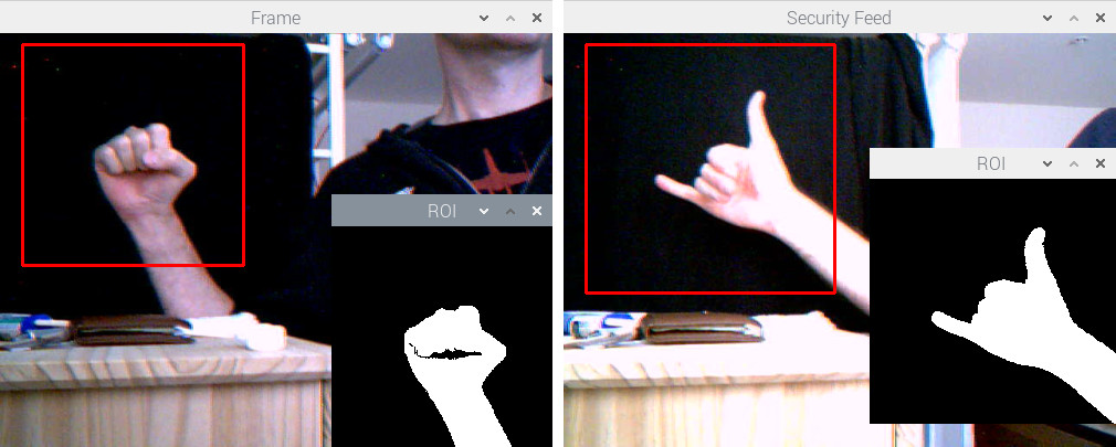
A binary mask to obtain hand gesture shape, to be trained for gesture recognition
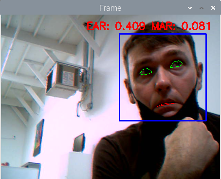
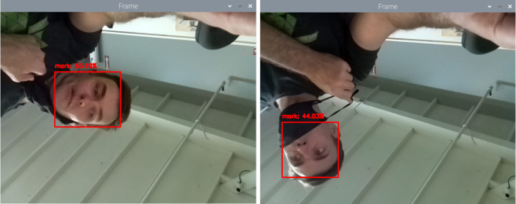
Notice the difference in probabilities associated with the face recognition predictions when the face is partially occluded by face mask
Eventually, I moved onto more complex projects, including programming an autonomous mini robot car that responds to commands based on what the AI algorithm infers from an attached camera’s video feed – This was real-time computer vision! There were many starter robot car kits to choose from. Some are for educational purposes, others come pre-assembled with a chassis, motor controllers, sensors, and even software. Surely, this was the best path for me to get straight into the software and image processing. But the pandemic had bogged down supply chains, and it seemed that any product with a microchip was on backorder for months.
A backlog of cargo ships waiting outside west coast ports as a symbol of supply chain issues
I couldn’t find a starter robot car kit for sale online that shipped within 60 days and I wasn’t willing to wait that long.And I didn’t want to skip this tutorial because it was a great exercise combining the RPi, AI, and Python programming triad. ACE Makerspace facilities came to the rescue again with the electronics stations and 3D printers which opened up my options.
I learned a few things working at computer vision hardware companies: Sometimes compromises are made in hardware due to availability of components; Sometimes compromises are made in the software due to the lack of time. One thing was for sure, I had to decide on an alternative hardware solution because hardware supply was the limiting factor. On the other hand, software was rather easy to modify to work with various motor controllers.
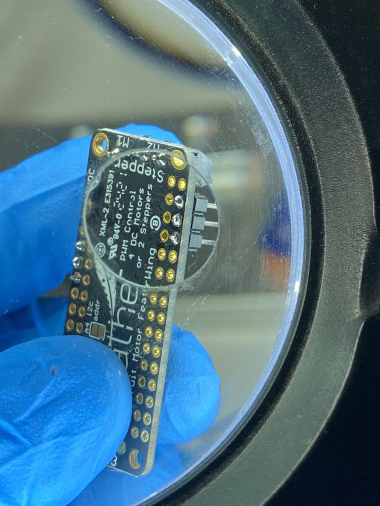
So after some research I decided on making my own robot car kit using the JetBot reference design. The JetBot is an open-source robot based on the Nvidia Jetson Nano, another single board computer more powerful than the RPi. Would this design work with the RPi? I ordered the components and shifted focus to 3D printing the car chassis and mounts while waiting for components from Adafruit and Amazon to arrive. ACE has (2) Prusa 3D printers on which I could run print jobs in parallel;
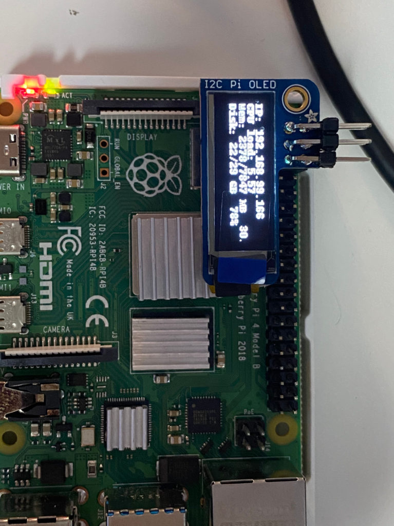
When the parts arrived I switched over to assembling and soldering (and in my case, de-soldering and re-soldering) the electronic components using ACE’s electronics stations equipped with many of the hand tools, soldering materials, and miscellaneous electrical components. When fully assembled, swapping in the Raspberry Pi for the Jetson Nano computer was simple and it booted up and operated as described on the JetBot site.
SolderingIt’s ALIVE! with an IP address that I use to connect remotely
The autonomous robot car starts by roaming around at a constant speed in a single direction. The Raspberry Pi drives the motor controls, operates the attached camera, and marshals the camera frames to the attached blue coprocessor, an Intel Neural Compute Stick (NCS), plugged into and powered by the Raspberry Pi USB 3.0 port. It’s this NCS that is “looking” for a type of object in each camera frame. The NCS is a coprocessor dedicated to the application-specific task of object detection using a pre-installed program called a MobileNet SSD – pre-trained to recognize a list of common objects. I chose the object type ‘bottle’.
“MobileNet” because they are designed for resource constrained devices such as your smartphone. “SSD” stands for “Single-shot Detector” because object localization and classification are done in a single forward pass of the neural network. In general, single-stage detectors tend to be less accurate than two-stage detectors, but are significantly faster.
The Neural Compute Stick’s processor is designed to perform the AI inference – accurately detecting and correctly classifying a ‘bottle’ in the camera frame. The NCS localizes the bottle within the camera frame and determines the bounding box coordinates of where in the frame the object is located. The NCS then sends these coordinates to the RPi; The RPi reads these coordinates, determines the center of the bounding box and whether that single center point is to the Left or Right of the center of the RPi’s camera frame.
Knowing this, the RPi will steer the robot accordingly by sending separate commands to the motor controller that drives the two wheels:
If that Center Point is Left of Center, then the motor controller will slow down the left wheel and speed up the right wheel;
If that Center Point is Right of Center, then the motor controller will slow down the right wheel and speed up the left wheel;
Keeping the bottle in the center of the frame, the RPi drives the car towards the bottle. In the lower-right corner of the video below is a picture-in-picture video from the camera on the Raspberry Pi. A ‘bottle’ is correctly detected and classified in the camera frames. The software [mostly] steers the car towards the bottle.
Older USB Accelerators, such as the NCS (v1), can be slow and cause latency in the reaction time of the computer. So there’s a latency in executing motor control commands. (Not a big deal for a tabletop autonomous mini-car application, but it is a BIG deal for autonomous cars being tested in the real world on the roads today.) On the other hand, this would be difficult to perform on the RPi alone, without a coprocessor, because the Intel NCS is engineered to perform the application-specific number-crunching more efficiently and while using less power than the CPU on the Raspberry Pi.
Finally, I couldn’t help but think that there was some irony in this supply chain dilemma that I had experienced while waiting for electronics to help me learn about robots; Because maybe employing more robots in factories will be how U.S. manufacturers improve resilience of supply chains if these companies decide to “onshore” or “reshore” production back onto home turf. Just my opinion.
Since finishing this robot mini-car I’ve moved on to learn other AI frameworks and even training AI with data in the cloud. My next challenge might be to add a 3D depth sensor to the robot car and map the room in 3D while applying AI to the depth data. A little while back I picked up a used Neato XV-11 robot vacuum from an ACE member, and I might start exploring that device for its LIDAR sensor instead.
Let me know if you’re interested in learning about AI or microprocessors, or if you’re working on similar projects. Until then, I’ll see you around ACE!
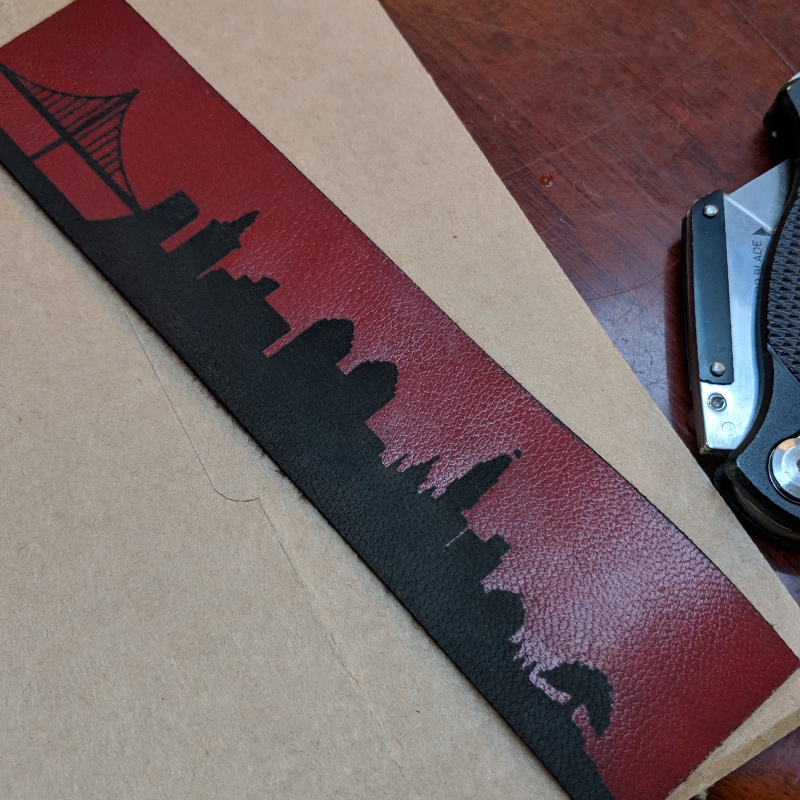
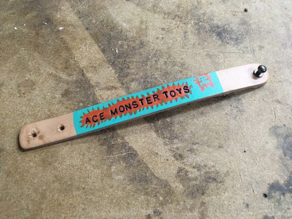
At the Golden Gate Library, families got together with us to experiment with leather-working skills, creating personalized bracelets.
Folk could choose from precut bracelets or leather scraps they cut themselves. We brought a wide range of stamps, paints, and hardware that each person used to individualize their very own wearable work of art.
Ted Huller is a long-time Ace member and also Ace’s resident 3D Printing Steward. I’m Carter Jenkins, and I had the chance to talk with Ted about his history with Ace as well as some recent work he has done.
Ted’s History with Ace
Ted is a long-time friend of Ace Executive Director Rachel Crafty, but Ted’s story begins before Rachel was in that role. Ted works in a laboratory, and throughout his working process, he sometimes finds that he needs to make custom-built parts in order to fulfill certain jobs. He normally would make these parts out of wood, (Ted is a master woodworker) but one day the job required a small beaker holder that was too fine to make with wood. Hearing about Ace’s 3D printing workspace, Ted decided that he should learn some basic skills in 3D printing so that he could handle situations like these. He admits the process wasn’t very smooth, but in the end, he had a working product, and that experience made Ted very interested in 3D printing as a whole.
Fast forward a few years, and Ted became a regular Ace member. He still did woodworking at home, but the Ace makerspace had become his new home for metalwork and some 3D printing. Ted quickly got his own 3D printer at home, meaning that his interactions with Ace slowly dwindled as his needs for printing materials shrunk. One day, however, former 3D printing steward Matt stepped down, leaving the position open to anyone in the Ace community. After some deliberation, Ted decided that he should give something back to the Ace community, and with his new expertise, Ted became the printing steward.
The 3D Printing Space at Ace
The 3D printing space is shared with a multipurpose space that houses the electronics lab, a couple of workstations, and the big format paper printer. This room is known as the Clean Fabrication room. There are two Prusa-brand 3D printers, which Ted calls “the Ford F-150 of printers. There’s a lot of them, they’re not the most sophisticated, but they’re pretty darn reliable and thought out.” There’s also a nearby computer dedicated to preparing files for the printers. The printers don’t need a computer to run, but makers will often find that it helps to be able to do last-minute manipulations to the 3D object files.
The Slack community for 3D printing at Ace has members in the hundreds, and pretty much all questions and discussions happen over Slack. Ted considers it the most efficient way to ask, read, and answer questions; he encourages new members to use Slack for almost all of their communications.
An Example of Ted’s Work
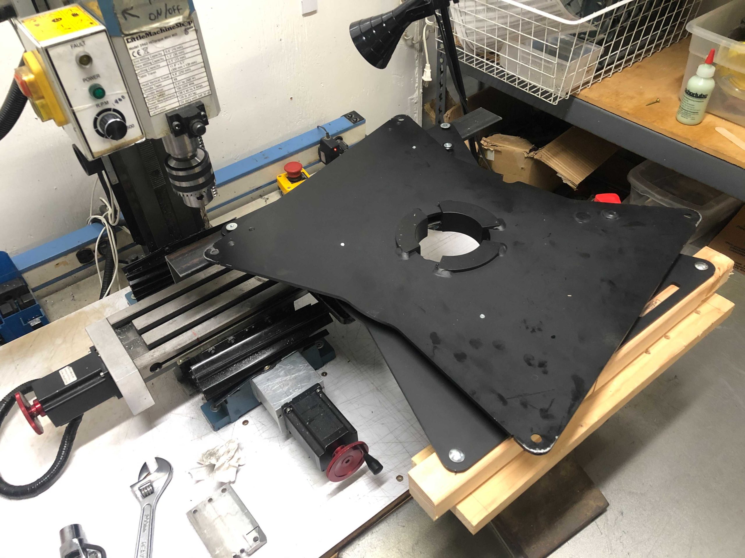
Some in-progress work being done at the Ace metal mill
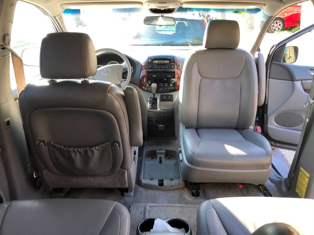
Ted and his wife recently bought an old minivan so they can go camping without having to deal with tents. The Toyota they bought was almost perfect for this purpose, except for one thing. The two of them both found the minivan to be a little too small to have both front seating and bed arrangements, so they looked into having adaptable seats that could swivel and lie down to make beds. The Toyota’s seats, however, were bolted to the floor in such a way that commercial seat-adjusting kits wouldn’t work. With no other options, Ted turned to his making skills to fabricate a “captain’s chair,” similar to those found in commercial RVs.
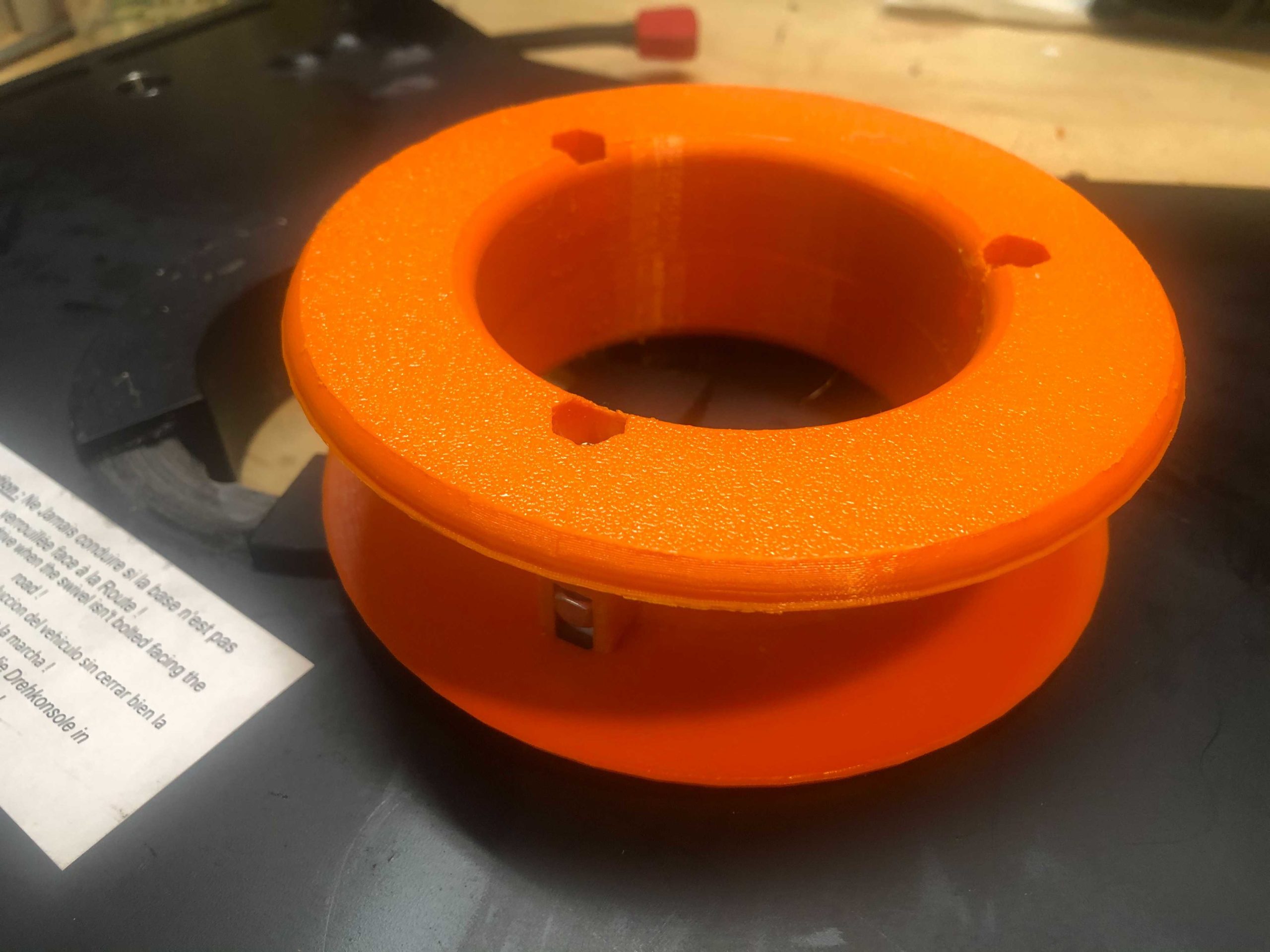
Ted started with drilling out a swivel plate and holes in the floor of the van, making sure to line them up precisely by means of the metal mill at Ace. The actual process of making the seat swivel wasn’t that difficult, but Ted encountered another problem soon after. Modern-day seats in cars and vans have lots of electrical wiring leading into them, whether it’s for operating a heater or controlling the seat’s back-and-forth movement. Ted found that the wires in the seat were dangerously close to shearing themselves on some exposed metal left by the drill holes, which would cause all sorts of maladies if not addressed properly. To solve this problem, he 3D printed a large plastic washer that bolts onto the wire hole. This means that instead of the wires dragging on sharp metal edges, it’s protected by a layer of comparably soft plastic. There were other little 3D-printed objects that Ted made, such as protective sheaths for the wire connectors.
An example of a bushing used in the project
Interestingly, Ted’s neighbor was going through a similar process with a van of their own at around this time. They had also encountered the same wire-cutting problem, and since Ted had just fitted the washer he offered to print a duplicate for his neighbor. With about a dollar’s worth of filament, Ted solved his neighbor’s problem.
Closing
Ted will continue to make and create at Ace for a long time. There are no big projects in his immediate future, but before our talk ended Ted told me that he was looking forward to, “training some more people, getting them ready, and seeing what people are going to 3D print.” I’m Carter Jenkins and thank you for reading.
Mauricio Salmerón has been working on a project recently. What started as a joke request to a friend has now spanned into a multi-month project that is now nearing completion. I got a chance to speak with Mauricio over a weekend and he shed some light on what other workshop members saw as two large pieces of wood glued together.
Mauricio has been an off-and-on member of the Ace Makerspace for a few years now. He used to own a furniture-making shop called “The Furniture Space,” where he did woodworking to create all kinds of custom furniture such as tables and sideboards. After that, Mauricio found Ace to be the best place to continue honing his craft.
A while back, Mauricio was talking with June, a friend of his. The conversation eventually drifted to June’s need for a new bed. After discussing how June’s search hadn’t been successful, Mauricio jokingly offered to build her a bed frame. The two laughed, and the conversation moved on. However, a month or two later June took Mauricio up on his half-serious request.
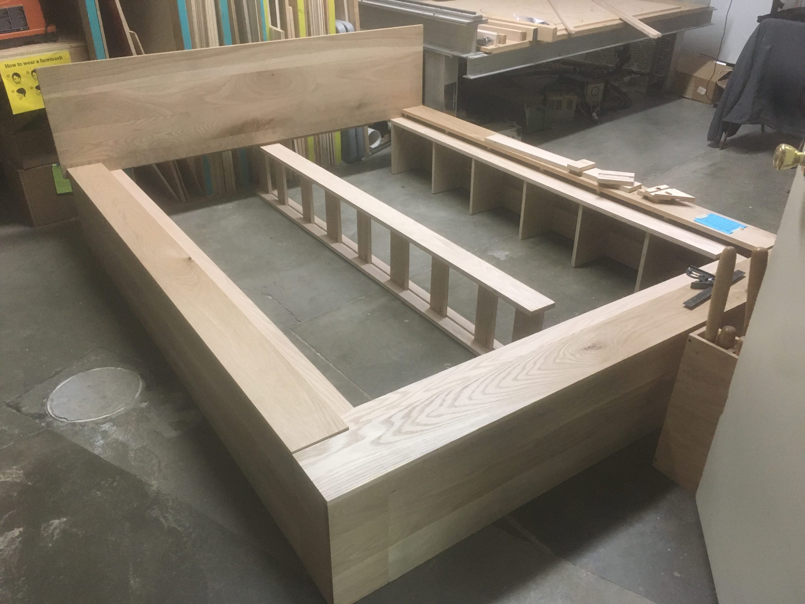
The bed frame, later in its construction phase
Mauricio worked on the project on and off, but many months later it’s nearly complete. Throughout his build process, Mauricio used many workshop tools to complete the project. The table saw, chop saw, router, drill, and planer to name a few. He estimates “another 10 hours of work and headboard assembly” and the new frame will be ready to send to June. The entire assembly consists of 5 main parts that can be put together to complete the full platform-style bed. June, of course, will have to provide the mattress, but it seems that the bulk of the work has been completed.
Process
Early pieces
Oak boards were surfaced through the joiner and planer, then dimensioned with the table saw
The boards were clamped together and glued to make the large sides of the bed, the tops to the sides with pocket screws
The three main pieces were completed by now, each with its own plywood support frame
Later pieces
The surfaced boards were put together with pocket screws and clamps to create the headboard
The last piece, the middle mattress support, was made with plywood, glue, and pocket screws
Final assembly
The three large oak pieces were attached with latches, the headboard had cleats and bolts to attach to the side pieces, and the middle mattress support piece
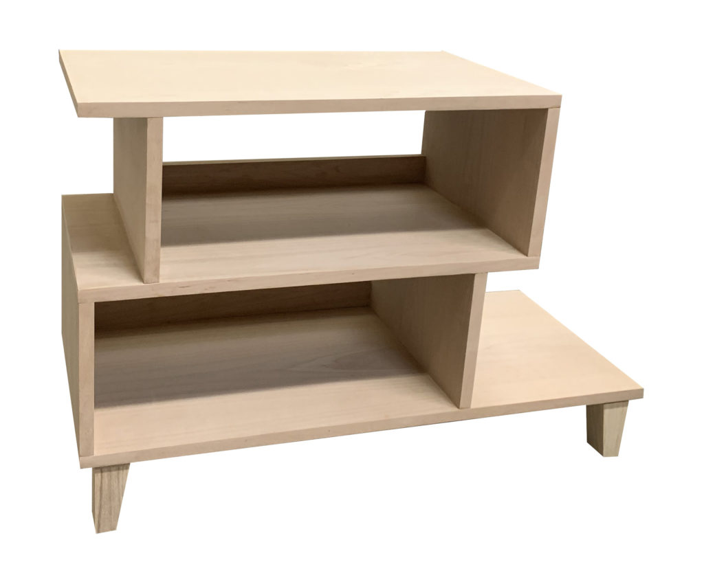
My 23 year old son told me he’d love a shoe rack in his new home that doubled as a side table for his sofa.He’d been unable to find anything to buy that fit the dimensions, so I decided to build him one.
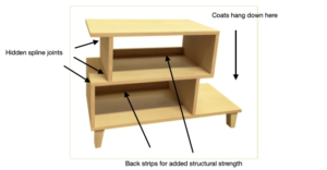
There were a few specifics that needed to be accounted for — the dimensions of the space, the color of wood that would complement his room, and the fact that they hang coats against the wall that the rack/table would abut…
He loves mid-century modern furniture — so I found and modified a style online to be able to hold 5 pairs of shoes, be the right height for the sofa table, and allow for the coats to co-exist.
I recently made a different shoe rack with mitered corners on the plywood sides — and was pretty unhappy with the results.Solid wood is so much more forgiving for the occasional minor gap in the joint — because you can sand it down to make the flaw less visible.I found plywood, however, having such a thin veneer, too easy to oversand and ended up with areas where the veneer was gone and the underlying ply exposed.
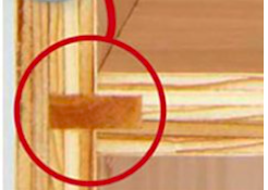
But I knew a plain butt joint wouldn’t provide enough stability.I decided instead to do two things to strengthen the joints in the plywood pieces:I created a hidden spline joint, and I added a 2″ back strip to each shelf to support the entire structure.
That left all the plywood edges exposed, which I’d planned to cover with iron-on edge veneer.In my cabinet-making days (decades ago!) I’d regularly made plywood shelves with edge veneer without problem.But in this project, this is where the headaches got the worst!
I ironed the edge veneer on each board before assembling the piece.The edge tape is 7/8″ wide, so there’s a good amount to remove till it’s the proper width for the plywood.I sanded each piece down, only to discover that I’d inadvertently sanded through the plywood veneer in places.
Additionally, once I put the pieces together, additional sanding went through parts of the edge veneer AND the plywood veneer!I cannot even count how many re-dos I did of the edge veneer — which was far more challenging now that the piece was assembled and everything had to fit exactly.
I finished the piece in oil based varathane to warm up the color a bit. In the end it came out okay.Most of the flaws were in the back, which won’t show being against the sofa. (My son was pleased, most importantly)
I’ve thought about how I’d do it differently next time.I don’t know how easily I could find a thicker veneered plywood, but I’d swear the veneer was thicker in the old days…!
I’d definitely invest in an edge veneer trimmer to lessen the sanding I was doing.
And I’ll likely lean more towards using solid wood vs plywood in future projects!


 Ted is a long-time friend of Ace Executive Director Rachel Crafty, but Ted’s story begins before Rachel was in that role. Ted works in a laboratory, and throughout his working process, he sometimes finds that he needs to make custom-built parts in order to fulfill certain jobs. He normally would make these parts out of wood, (Ted is a master woodworker) but one day the job required a small beaker holder that was too fine to make with wood. Hearing about Ace’s 3D printing workspace, Ted decided that he should learn some basic skills in 3D printing so that he could handle situations like these. He admits the process wasn’t very smooth, but in the end, he had a working product, and that experience made Ted very interested in 3D printing as a whole.