Category: Electronics

All the electronics stuff, microprocessors and more

LED lit, laser-cut stage with performers

Greg’s Laser-Cut Plywood and LED Stage Build

This summer, I had the opportunity to design and build one of the stages for a small annual festival. I’d just returned from a 3-week bike tour through Portugal and Southern Spain, where I’d seen an abundance of amazing historical buildings, from cathedrals to ancient fortresses.

Inspired by the amazingly elaborate details and layers of cultural influence in the architecture I’d seen, I wanted to create an intricate laser-cut plywood design that incorporated LED strips for nighttime stage lighting, but that still looked visually interesting during the daytime performances. It also had to be built ahead of time and easily assembled on-site.
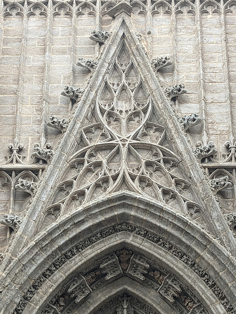
Catedral de Sevilla
Architectural detail on the Catedral de Sevilla; one of my main reference photos for design elements to use in the stage design.

I originally planned to use Rhino with Grasshopper for creating the design. Grasshopper provides a node-based way of scripting parametric models, and I’ve seen people make some incredible computational designs using it in combination with Rhino. Although I’d really like to learn how to use these programs, and they would have been a good fit for this project, due to time constraints, I stuck to the skills I already have from my background as a mechanical engineer. This meant using OnShape, an online Computer Aided Design (CAD) modeling program like SolidWorks or Autodesk Inventor.

To those unfamiliar with CAD tools that use parametric modeling, it works a bit differently than tools like Illustrator or Paint where you create the design directly. With parametric modeling, you define a series of geometric constraints, dimensions and formulas that define the shapes you’re trying to create.

Parametric models work a little bit like complex equations or a software code, in that it takes time to set them up, but once you do you can go back and adjust the inputs to get near-instant updates without having to recreate or manually tweak the design.

With parametric modeling, as when writing software, it’s good to follow the principle of, “DRY – Don’t Repeat Yourself.”

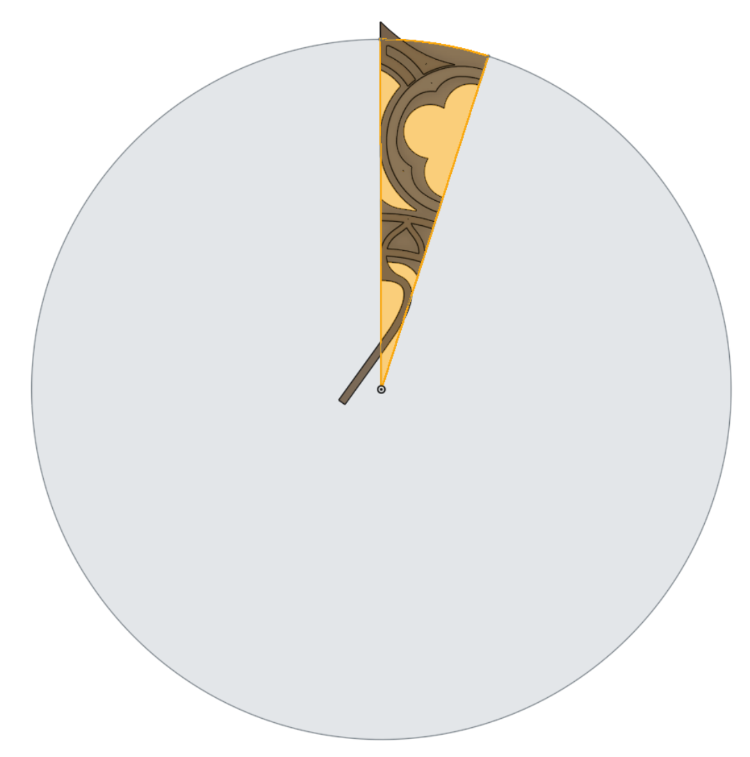
For the rose window element design, the first step was to look for any symmetries. In this case, it meant identifying the smallest “unit cell” that could be replicated to create the full design through mirroring, copying and patterning it. Fortunately every CAD tool has built-in commands to mirror and to rotationally pattern a part. These built-in commands make it easy to create the full piece from a smaller, simpler “unit cell,” while being able to update the original and see how it would look when patterned.
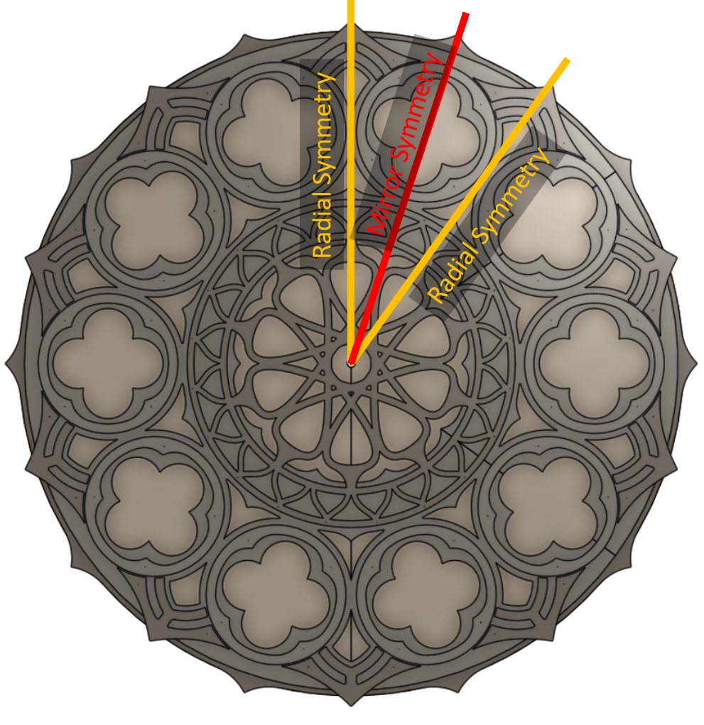
Overview of a rose window design, with lines showing the radial and mirror symmetry axes
Radial and symmetry axes of the rose window design.
A unit cell of a rose window design.
Rose window unit cell.


Creating a model for the pillars was more difficult. I wanted to be able to pattern a design along a gentle curve while having it adapt to the width between the curve and the centerline. There’s no built-in CAD command to pattern a part while changing the inputs that define the part (well, there is kind of but not in a way I was able to make work for this design). Instead, I set up a part for the pillar unit cell with different “configurations” where each configuration had the height and width of the bounding shape matching those measured along the curve. This was still a somewhat manual process because, if I changed the shape of the curve, I had to update the width and height of each part configuration to get it to match. That being said, with the curve fixed, I was able to change a single design and have all the instances of the unit cell update—my desired result. It’s worth noting that OnShape actually has its own scripting language, FeatureScript, which I could have used to write a custom command for the result I had hoped to achieve, but didn’t have the time. I plan to explore this approach more in the future.
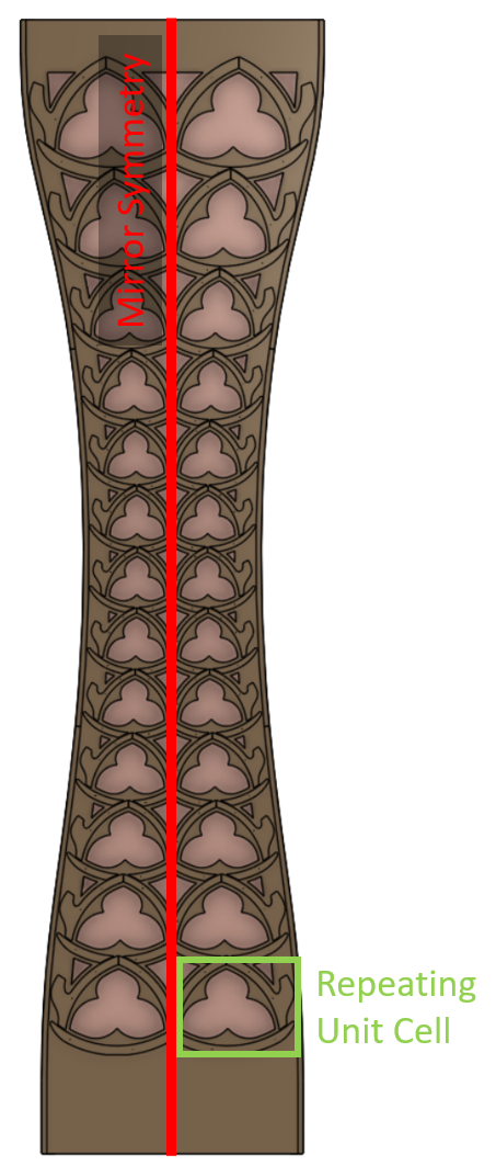
Diagram of rose window column, lines indecating "mirror symetry" and "repeating unit cell."
Identifying symmetry and unit cell pattern in the pillar design.
Unit cell
Configurable “unit cell” for the pillar.

All this modeling was to make the files required for the laser cutter, which reads 2D line drawings.

Someone who is proficient at a vector art tool like Illustrator likely could have created the same final design in 1/10th the time it took me to set up this complicated parametric CAD model. That being said, I had fun modeling it this way and I got more familiar with OnShape along the journey!

Once I was happy with the design (by which I mean out of time to continue tweaking it), I exported everything and headed to the laser cutter.

Laser cutting mostly went smoothly, although it took two passes to get all the way through the 1/4″ birch plywood. The main issue for the bigger parts was just getting the plywood to lay flat enough to keep the laser in-focus. I used every magnet in the drawer and could have used even more!

I hit a snag with the high-quality “Exterior Grade” Baltic Birch Plywood I had originally purchased for the project from MacBeath Hardwood. Whatever the manufacturer treated it with to make it exterior grade, prevented the laser from cutting past the first glue layer. After having made this expensive error, I bought the cheaper 4×8′ regular “White Birch” sheets from MacBeath, which they helped me rip into thirds that fit nicely into both the laser-cutter work area and the back of my car. The total cut time was approximately 200 minutes, spread out across several long, late-night sessions. It took far more time to layout and fixture the cuts than actual active cutting time.
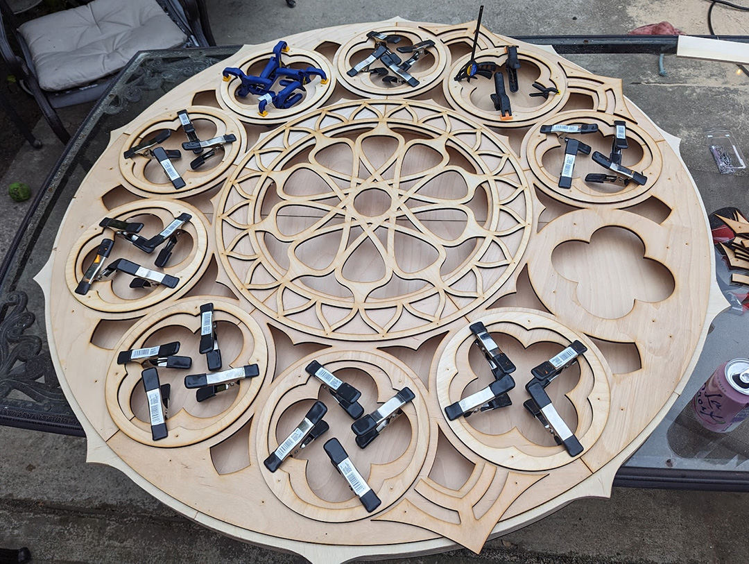
Rose Window glueup
Glue layup of the rose window element; could have used even more clamps.

The final assembled pieces have a solid back spaced 1.5″ from the front cutout parts. I cut “rib” parts out of 3/4″ plywood and doubled them up to get the 1.5″ spacing. I then joined the parts with wood glue and a nail gun (the nails are invisible from far away and provided good clamping force while the wood glue dried). This resulted in surprisingly light and stiff parts.

I created the detail on the front of the panels by gluing on smaller parts. This layup was challenging due to the sheer quantity of small parts.

For the pillars where the unit cell had many unique configurations, there were literally hundreds of small parts that all had to go in specific locations!

I added pre-fabricated holes to the laser-cut patterns for small brad nails which made it easy to align the small parts during assembly, and keep everything from sliding around during the glue-up. Once the glue was mostly dried I removed the brad nails so they wouldn’t become a permanent part of the assembly. The back panels are removable for installation and maintenance of LED strips glued along the inside face of the ribs. I used a silicone caulk for the LEDs, which works well as long as the ends of each LED strip are securely attached. The silicone caulk is strong enough to keep the strips in place, but easy to peel off if necessary.
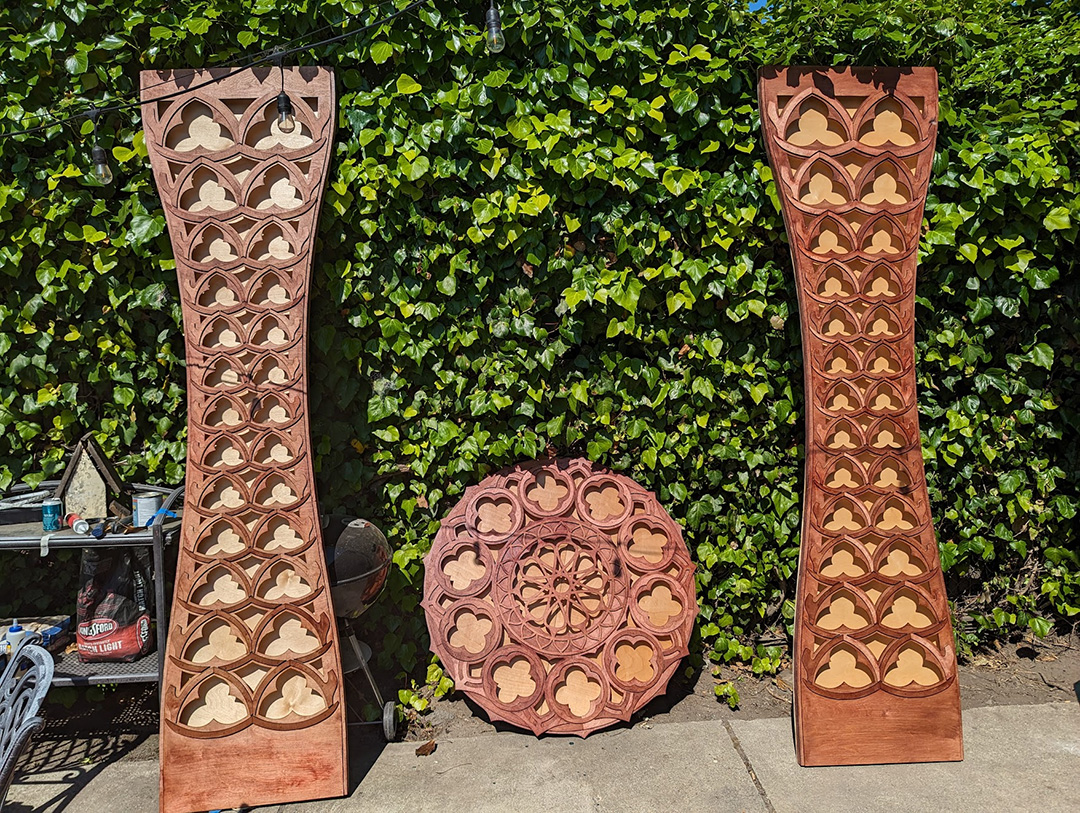
Laser-cut pillars
Finished and stained panels.

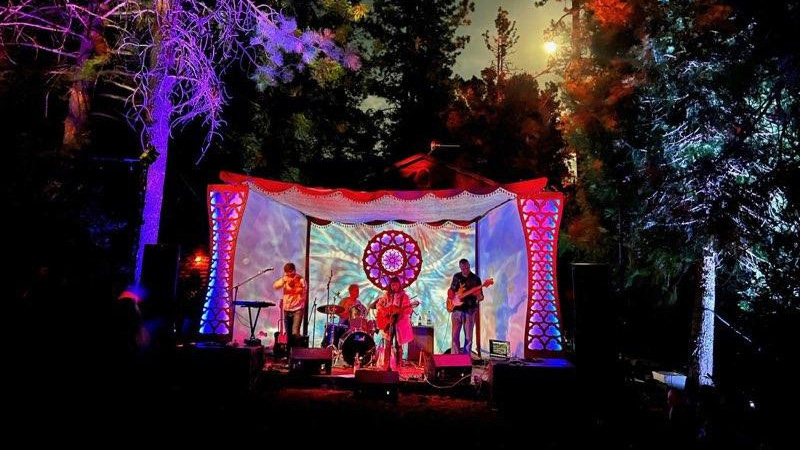
At the festival, the pieces were in the capable hands of Radiant Atmospheres, an event lighting collective practically next door to Ace. They hooked up the LED strips to a DMX decoder, which let them control them from the same system they were using to drive the rest of the stage lighting and effects. They also brought two rear projection units that set up an ever-shifting psychedelic pattern on the stage backdrop. I was really impressed with the work they did; it’s a bit hard to capture in photos but the stage lighting was gorgeous. All-in-all I’m pleased with how this project came out, and excited to take lessons learned and continue to play with the laser-cutter and other tools at Ace!
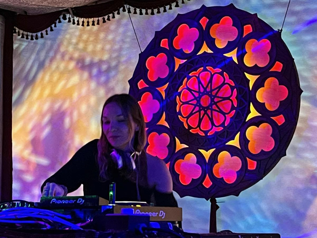
DJ performing in front of the rose window element
Ukrainian artist “Asymmetry” performing with the rose window element behind.

Oh, and the band in the cover image is the enchanting Foxtails Brigade!

What worked:

  • The alignment holes and brad nails made the glue-up substantially easier; it would have been a real nightmare to get things lined up without them.
  • In the design I left strategic gaps between parts to create the illusion that some parts were behind others, even though they were on the same layer. This visual trickery seemed to work; I had a few folks tell me they were surprised that it only had two layers.
  • I loved the effect of the indirect LED lighting on the back panel, especially the regions lit by two different LED strips. It created smooth gradients that I thought were beautiful. The default with LED art is to create more complexity by adding an ever-increasing density of LEDs, but in this case I think less was more. It’s only five unique colors for all three of the panels, but the natural blending on the back panel made it seem more complex than it was. A happy accident of the constraints of the materials/budget I had to work with!

What could be improved:

  • Creating the design out of hundreds of small parts made assembly incredibly time consuming. Designing for fewer, larger parts with more complexity per part would have cut down on the time it took to assemble everything.
  • The ribs between the front and back layers were time consuming to make; I “scored” lines onto thick plywood with a light laser pass and then cut them out with a jigsaw at home. This took a long time and was difficult to do accurately, even with the precise guide lines created on the laser cutter. If I were certified on the CNC machine at Ace, that would have been a better way to go. Fortunately, the closest audience members were approximately 15′ away, and most of the mistakes were invisible from that distance.
  • In hindsight, it would have been interesting to score inset lines from the edges of the parts on the laser-cutter; that would have been an easy way to suggest even more depth & visual interest.

Coworking for Computer Vision

Hi, my name is Mark. I’ve been a member of ACE for almost 9 years. There’s been three things on my To-Do list gnawing at my psyche for some time:

  1. Learn about Raspberry Pi microprocessors through Internet of Things (IoT) applications.
  2. Get hands-on experience with Artificial Intelligence.
  3. Learn the popular Python programming language.

Why these? Because computers are getting smaller while getting more powerful; Artificial Intelligence (AI) is running on ever smaller computers; and Python is a versatile, beginner-friendly language that’s well-documented and used for both Raspberry Pi (RPi) and AI projects.

I’ve been working in computer vision, a field of AI, for several years in both business development and business operations capacities. While I don’t have a technical background, I strive to understand how the engineering of products & services of my employers works in order to facilitate communication with clients. Throughout my career I’ve asked a lot of engineers a lot of naive questions because I’m curious about how the underlying technologies come together on a fundamental level. I owe a big thanks to those engineers for their patience with me! It was time for me to learn it by doing it on my own.

Computer Vision gives machines the ability to see the world as humans do – Using methods for acquiring, processing, analyzing, and understanding digital images or spatial information.


In starting on my learning journey I began a routine of studying at our ACE Makerspace coworking space every week to be around other makers. This helped me maintain focus after the a pandemic induced a work-from-home lifestyle that left me inhibited by a serious brain fog.

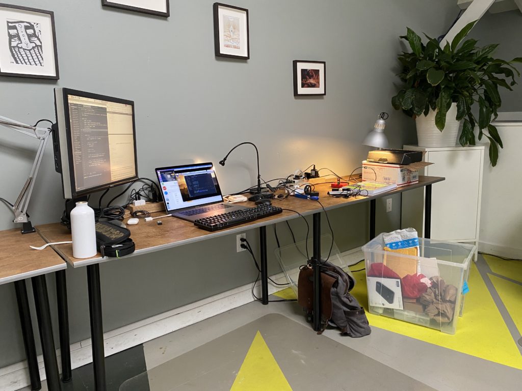
My work environment at ACE Coworking

OpenCV (Open Source Computer Vision Library) is a cross-platform library of programming functions mainly aimed at real-time computer vision. AMONG MANY COMPONENTS It includes a machine learning library as a set of functions for statistical classification, regression, and clustering of data.

Fun Fact: Our ACE Makerspace Edgy Cam Photobooth seen at many ACE events uses an ‘Edge Detection’ technique also from the OpenCV Library.

A self-paced Intro to Python course came first. Then came a course on OpenCV which taught the fundamentals of image processing. Later still came tutorials on how to train a computer to recognize objects, and even faces, from a series of images.
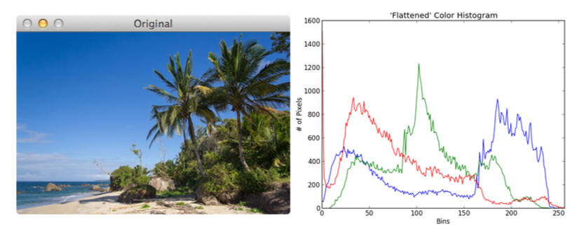
Plotting the distribution of color intensities in the red, green, and blue color channels


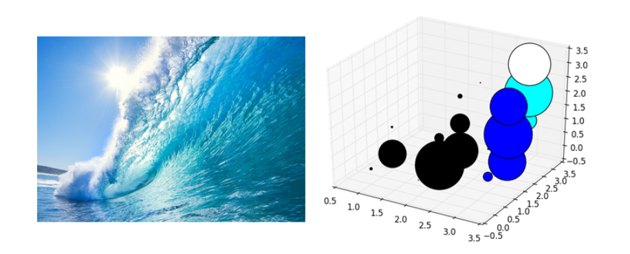
3D scatter plot of distributions of grouped colors in images


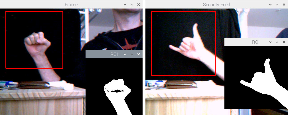
A binary mask to obtain hand gesture shape, to be trained for gesture recognition


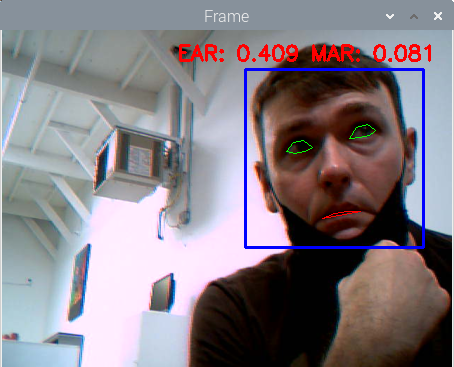
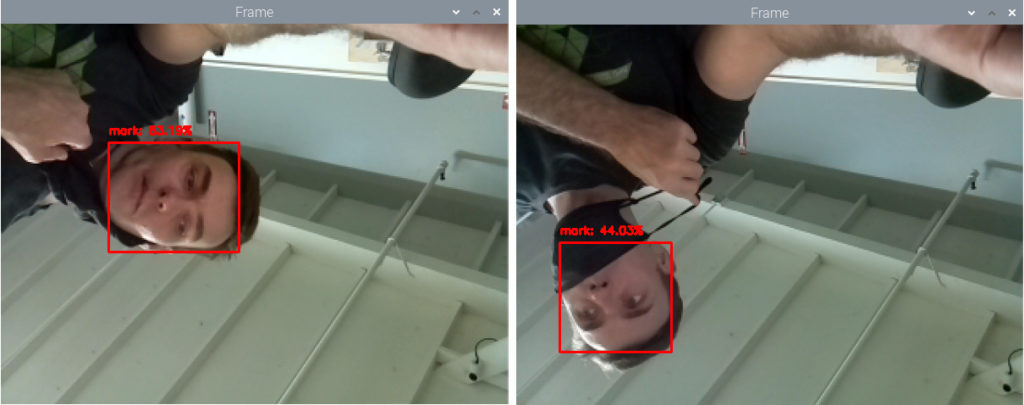
Notice the difference in probabilities associated with the face recognition predictions when the face is partially occluded by face mask

Eventually, I moved onto more complex projects, including programming an autonomous mini robot car that responds to commands based on what the AI algorithm infers from an attached camera’s video feed – This was real-time computer vision! There were many starter robot car kits to choose from. Some are for educational purposes, others come pre-assembled with a chassis, motor controllers, sensors, and even software. Surely, this was the best path for me to get straight into the software and image processing. But the pandemic had bogged down supply chains, and it seemed that any product with a microchip was on backorder for months.

A backlog of cargo ships waiting outside west coast ports as a symbol of supply chain issues

I couldn’t find a starter robot car kit for sale online that shipped within 60 days and I wasn’t willing to wait that long. And I didn’t want to skip this tutorial because it was a great exercise combining the RPi, AI, and Python programming triad. ACE Makerspace facilities came to the rescue again with the electronics stations and 3D printers which opened up my options.

I learned a few things working at computer vision hardware companies: Sometimes compromises are made in hardware due to availability of components; Sometimes compromises are made in the software due to the lack of time. One thing was for sure, I had to decide on an alternative hardware solution because hardware supply was the limiting factor. On the other hand, software was rather easy to modify to work with various motor controllers. 

So after some research I decided on making my own robot car kit using the JetBot reference design. The JetBot is an open-source robot based on the Nvidia Jetson Nano, another single board computer more powerful than the RPi. Would this design work with the RPi? I ordered the components and shifted focus to 3D printing the car chassis and mounts while waiting for components from Adafruit and Amazon to arrive. ACE has (2) Prusa 3D printers on which I could run print jobs in parallel;


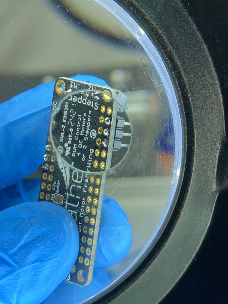
When the parts arrived I switched over to assembling and soldering (and in my case, de-soldering and re-soldering) the electronic components using ACE’s electronics stations equipped with many of the hand tools, soldering materials, and miscellaneous electrical components. When fully assembled, swapping in the Raspberry Pi for the Jetson Nano computer was simple and it booted up and operated as described on the JetBot site.

Soldering
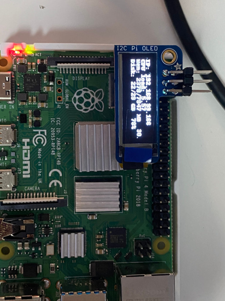
It’s ALIVE! with an IP address that I use to connect remotely

The autonomous robot car starts by roaming around at a constant speed in a single direction. The Raspberry Pi drives the motor controls, operates the attached camera, and marshals the camera frames to the attached blue coprocessor, an Intel Neural Compute Stick (NCS), plugged into and powered by the Raspberry Pi USB 3.0 port. It’s this NCS that is “looking” for a type of object in each camera frame. The NCS is a coprocessor dedicated to the application-specific task of object detection using a pre-installed program called a MobileNet SSD – pre-trained to recognize a list of common objects. I chose the object type ‘bottle’.
“MobileNet” because they are designed for resource constrained devices such as your smartphone.  “SSD” stands for “Single-shot Detector” because object localization and classification are done in a single forward pass of the neural network. In general, single-stage detectors tend to be less accurate than two-stage detectors, but are significantly faster.

The Neural Compute Stick’s processor is designed to perform the AI inference – accurately detecting and correctly classifying a ‘bottle’ in the camera frame. The NCS localizes the bottle within the camera frame and determines the bounding box coordinates of where in the frame the object is located. The NCS then sends these coordinates to the RPi; The RPi reads these coordinates, determines the center of the bounding box and whether that single center point is to the Left or Right of the center of the RPi’s camera frame.

Knowing this, the RPi will steer the robot accordingly by sending separate commands to the motor controller that drives the two wheels:

  • If that Center Point is Left of Center, then the motor controller will slow down the left wheel and speed up the right wheel;
  • If that Center Point is Right of Center, then the motor controller will slow down the right wheel and speed up the left wheel;

Keeping the bottle in the center of the frame, the RPi drives the car towards the bottle. In the lower-right corner of the video below is a picture-in-picture video from the camera on the Raspberry Pi. A ‘bottle’ is correctly detected and classified in the camera frames. The software [mostly] steers the car towards the bottle.

Older USB Accelerators, such as the NCS (v1), can be slow and cause latency in the reaction time of the computer. So there’s a latency in executing motor control commands. (Not a big deal for a tabletop autonomous mini-car application, but it is a BIG deal for autonomous cars being tested in the real world on the roads today.) On the other hand, this would be difficult to perform on the RPi alone, without a coprocessor, because the Intel NCS is engineered to perform the application-specific number-crunching more efficiently and while using less power than the CPU on the Raspberry Pi.

Finally, I couldn’t help but think that there was some irony in this supply chain dilemma that I had experienced while waiting for electronics to help me learn about robots; Because maybe employing more robots in factories will be how U.S. manufacturers improve resilience of supply chains if these companies decide to “onshore” or “reshore” production back onto home turf. Just my opinion.

Since finishing this robot mini-car I’ve moved on to learn other AI frameworks and even training AI with data in the cloud. My next challenge might be to add a 3D depth sensor to the robot car and map the room in 3D while applying AI to the depth data. A little while back I picked up a used Neato XV-11 robot vacuum from an ACE member, and I might start exploring that device for its LIDAR sensor instead.

Let me know if you’re interested in learning about AI or microprocessors, or if you’re working on similar projects. Until then, I’ll see you around ACE!

Mark Piszczor
LinkedIn

Light-up Holiday Cards at the Library

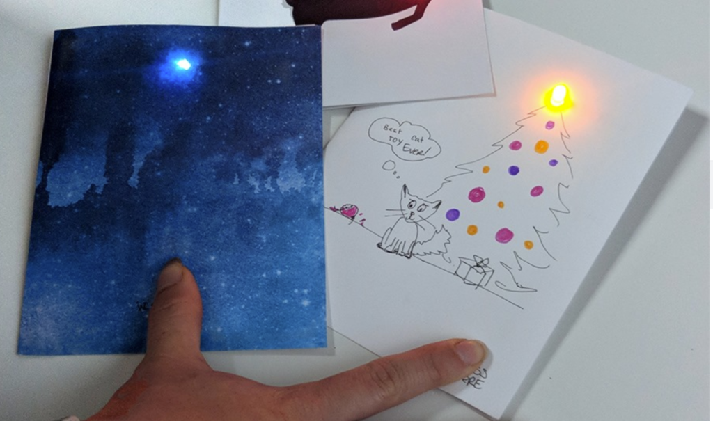
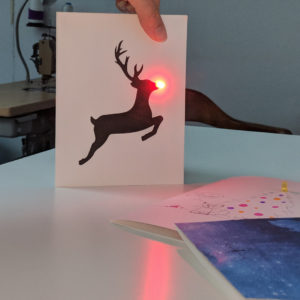
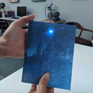
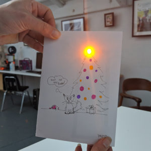
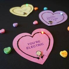
We had a blast making light-up holiday and birthday cards with families at the Golden Gate Branch Library. Each person started by designing their very own circuit with 1 to 4 LED lights, a battery, and a switch. Pushing the switch lit up the card!

Reindeer games!
Lighting up the night sky
Cats and christmas trees… need we say more?


Some folk crafted their own pictures, while others added lights to art paper. Either way, each person brought their own spark to the experience.

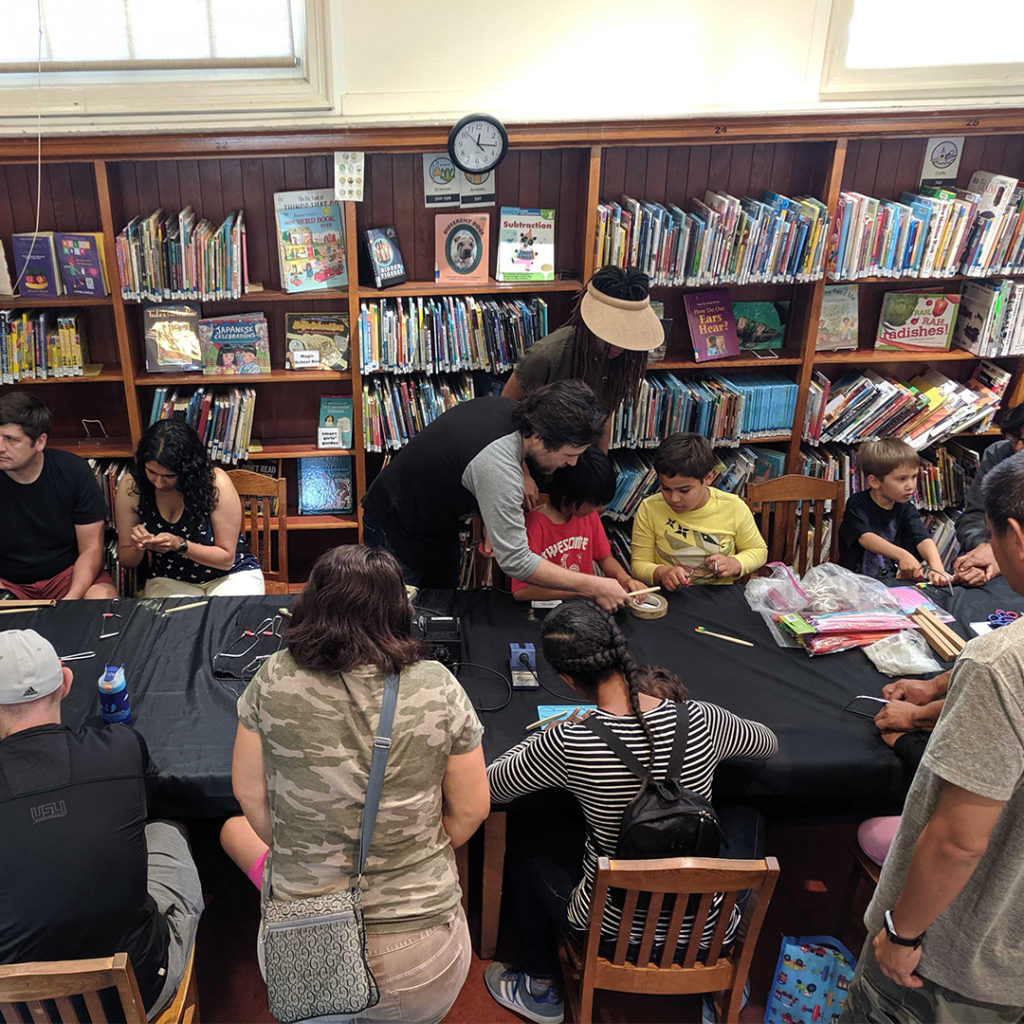
Bristle Bots at the library

Pet Robots at the Library

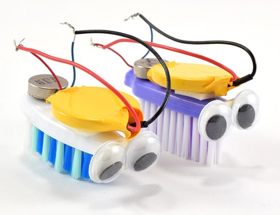
Bristle Bots are adorable critters made of googly eyes on a bristle-brush body that wiggle and dance their way across any smooth surface. Through a basic motor, these little guys vibrate their bristles and move!

Families joined us at the Golden Gate Library to make their very own Bristle Bot pets. We built the bodies using toothbrushes, hand saws, hot glue, soldering irons, and sandpaper, then each person decorated their dancing pet to give it its own unique personality. Then, participants got to race their bots against each other!

Made at AMT-June 2019

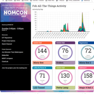
NOMCOM Fob All The Things dashboard | AMT Software • Bodie/Crafty
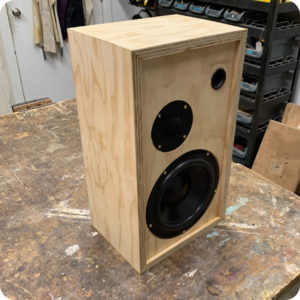
Hand Built Speaker | Workshop • David
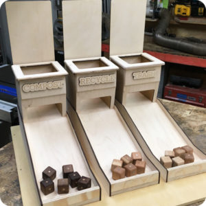
Recycling Game | Workshop/Laser • Bernard M.
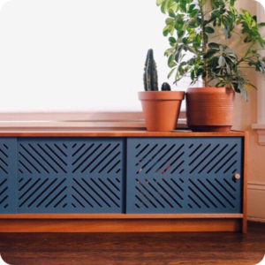
Solid wood credenza | Workshop | Raj J.
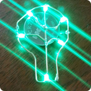
Tiny electronic brass jewelry | Electronics | Ray A.
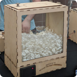
RFID Mint Dispensing Box | Laser+Electronics | Crafty
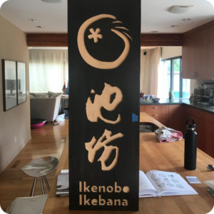
Wood Signage | CNC Router | James L.
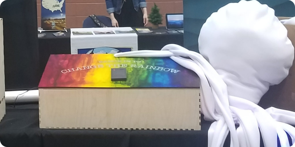
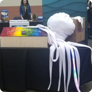
Fabric Kraken stuffed with 720 LEDs | Textiles + Electronics | Crafty

Programmable LED Costume Props at the Library

At the Golden Gate Library, we got together with folks to make programmable LED costume props.

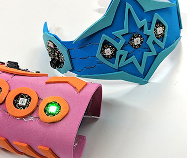
We had a variety of laser-cut kits for folks to choose from, including cuff bracelets, tiaras, and more. Folks then sewed conductive thread, microcontrollers, and LEDs to create and customize their programmable costume prop. This project is geared toward makers 14 and up.

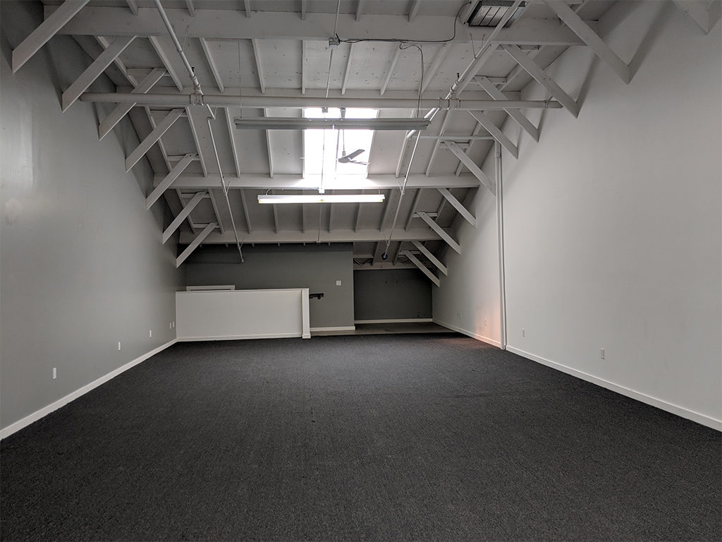
Big empty room

AMT Expansion 2018

This month AMT turns 8 years old and we are growing! We have rented an additional 1200sqft suite in the building. We have a Work Party Weekend planned June 1-3 to upgrade and reconfigure all of AMT. All the key areas at AMT are getting an upgrade :

CoWorking and Classroom are moving in to the new suite. Rad wifi, chill space away from the big machines, and core office amenities are planned for CoWorking. The new Classroom will be reconfigurable and have double the capacity.

Textiles is moving upstairs into the light. The room will now be a clean fabrication hub with Electronics and 3D Printing both expanding into the space made available. Photo printing may or may not stay upstairs — plans are still forming up.

Metal working, bike parking, and new storage including the old lockers will be moving into the old classroom. But before they move in the room is getting a face lift by returning to the cement floors and the walls will get a new coat of paint.

The CNC room and workshop will then be reconfigured to take advantage of the space Metal vacated. We aren’t sure what that is going to look like beyond more workspace and possibly affordable storage for larger short term projects.

Town Hall Meeting May 17th • 7:30PM • Plan the New Space

What expansion means to membership

The other thing that happened in May is after 8 years our rent finally went up. It is still affordable enough that we get to expand. Expansion also means increasing membership volume to cover the new rents and to take advantage of all the upgrades. We are looking to add another 30 members by winter.  Our total capacity before we hit the cap will be 200 members. We feel that offering more classes and the best bargain in co-working will allow us to do this. Please help get the word out!

The New Suite in the Raw

Big empty room

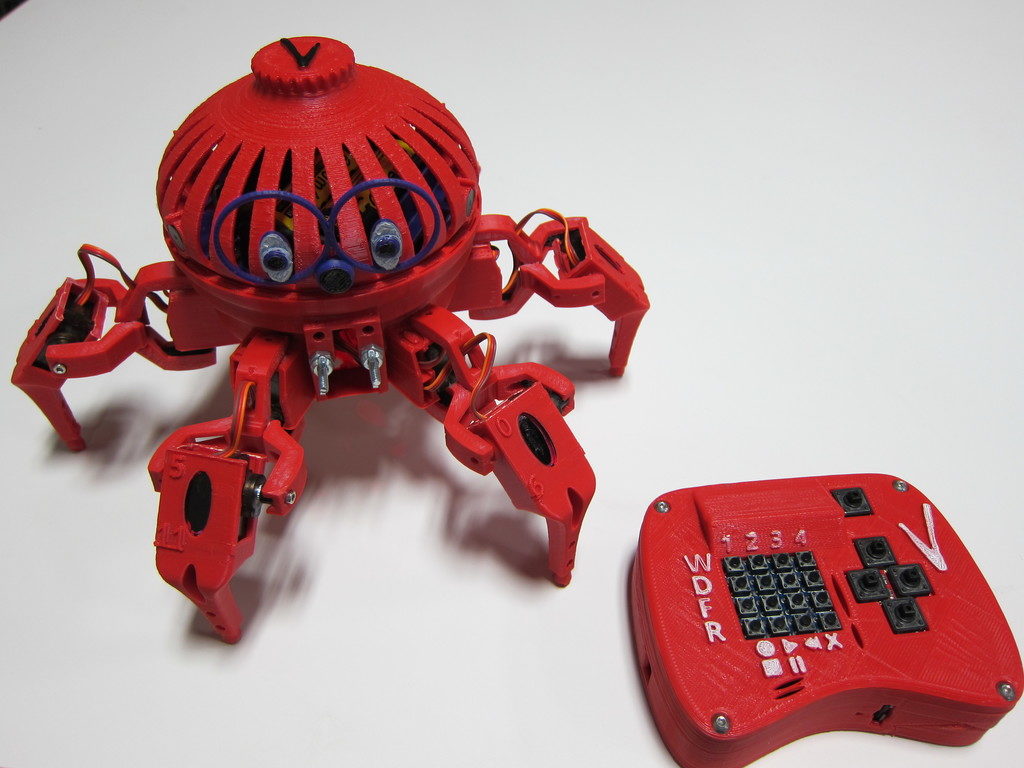
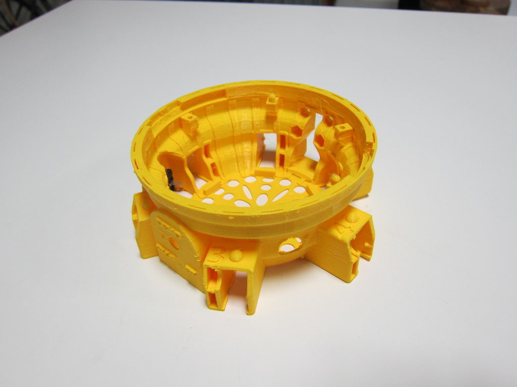
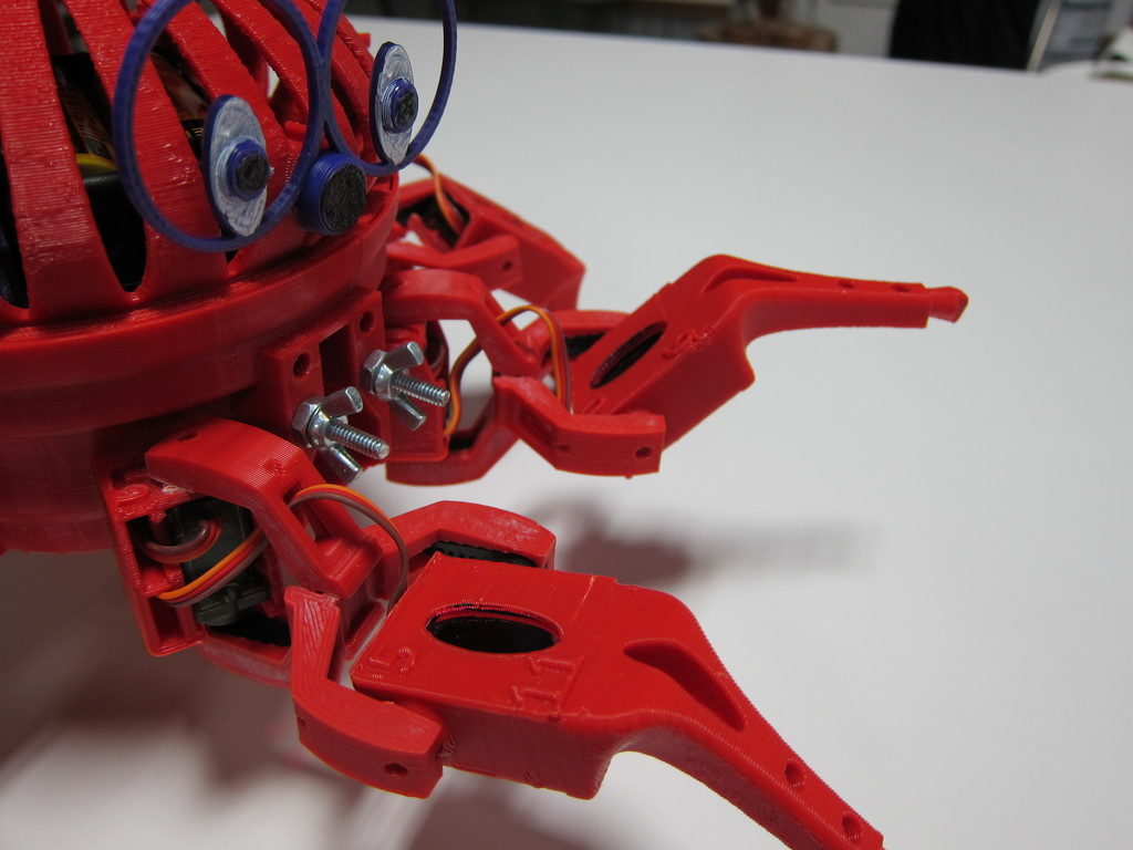
The Vorpal Combat Hexapod

I demonstrated this fun robot at the last BoxBots build night and our general meeting last Thursday. Since then a few folks have asked questions so I thought I would post more detail.

The Vorpal Combat Hexapod is the subject of a Kickstarter campaign I discovered a few weeks ago. I was impressed and decided to back the project. I had a few questions so I contacted the designer, Steve Pendergrast. Then I had a few suggestions and before long we had a rich correspondence. I spent quite a bit more time than I’d expected to, offering thoughts for his wiki, design suggestions, etc.

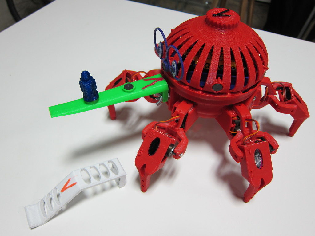
Steve appreciated my feedback and offered to send me a completed robot if I would promise to demonstrate it for our membership. The robot you see in the photos was made by Steve, not me. Mine will be forthcoming!

You can read the official description on the Kickstarter page and project wiki. Here are my own thoughts and a few of the reasons I like the project so much.

It’s cool!

It has to be to get the kids interested; something that Ray has always understood with BoxBots. While BoxBots offers the thrill of destructive combat, the hexapod offers spidery, insect-ish, crawly coolness with interactive games and programming challenges.

It’s a fun toy

Straight away, this robot offers lot of play value. There are four walk modes, four dance modes, four fight modes, and a built-in record/playback function. To get them interested in the advanced possibilities, you have to get them hooked first. Don’t be intimidated by that array of buttons. At the Boxbots build night, the kids all picked it up very quickly. I couldn’t get the controller out of their hands.

It’s open-source

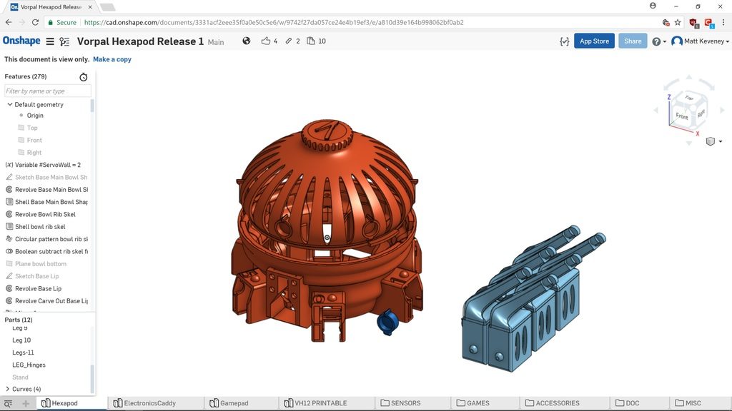
The circuitry, firmware, and plastic parts are already published. A lot of crowd-funded projects promise release only after funding, and some only publish the STL files, which can be very difficult to edit. Steve has provided the full CAD source (designed in OnShape).

Easy to Accessorize

The Joust and Capture-the-flag games use special accessories that fasten to a standard mount on the robot’s nose. This simplifies add-on design since there’s no need to modify the robot frame. There are also magnets around the perimeter, encouraging fun cosmetic add-ons like eyes and nametags.

Off-the-shelf electronic components

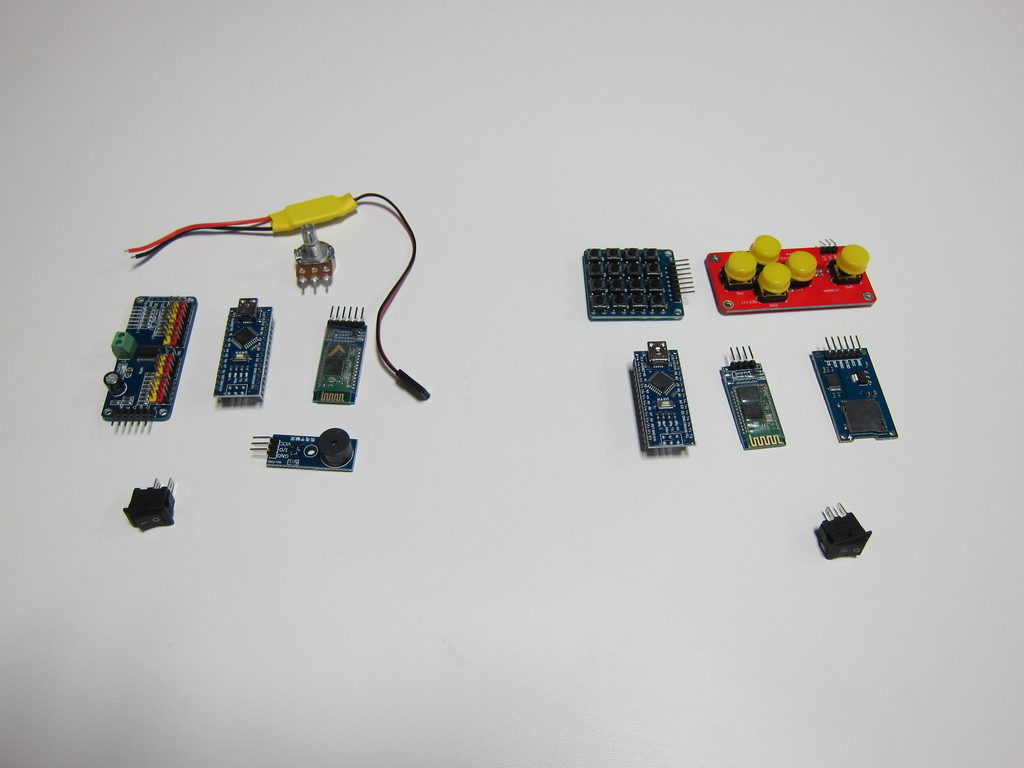
There are no custom circuit boards here. It’s built with two Arduino Nano boards, two Bluetooth boards, a servo controller, buzzer, pot, micro-SD adapter, two pushbutton boards, inexpensive servos, etc. This stuff is all available online if you want to source your own parts. If you’re an Arduino geek, it will all look familiar.

No Soldering!

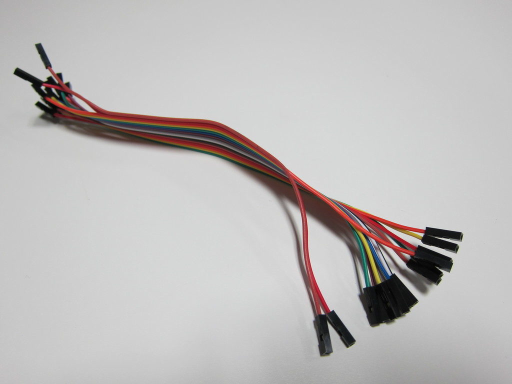
I think every kid should learn how to use a soldering iron in school, but for some it remains an intimidating barrier. In the hexapod, everything’s connected with push-on jumper wires. (If you source your own parts you will probably have to solder the battery case and switches, since these seldom have matching connectors.)

Scratch programming interface

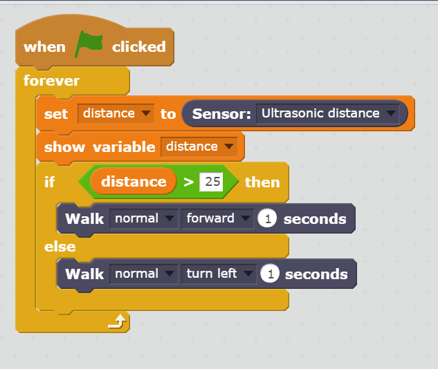
The controller and robot firmware is written in Arduino’s C-like language, but the robot also supports a beginner-friendly drag-and-drop programming interface built with MIT’s Scratch system. I confess, I haven’t investigated this feature yet, but I’ve been curious about drag-and-drop programming paradigms for years. My first programs were stored on punched cards. Finally, I have an opportunity to see how today’s cool kids learn programming!

It’s 3D printed

The parts print without support, and work fine at low-resolution. You’ll want to get your own spool of filament so you have the color available for replacement parts. Any of our printers will work. I’ve had good luck so far with PLA, but Steve recommends more flexible materials like PETG or ABS.

Anyway, enough gushing. I do not have any financial interest in the project. I just like to encourage a good idea when I see one. The Kickstarter campaign just reached its goal a few days ago, so it’s definitely going to be funded. If you’d like to back the Kickstarter or learn more, here’s the link. You’ll have to act fast; there are only a few days left. (Full disclosure: I do get referral perks if you use this link.) Remember that you always assume some risk with crowd-funding. I’ll make no guarantees, but I’m satisfied that Steve is serious about the project and is no scammer.

Click here for the Hexapod Kickstarter campaign.

If you’d like to see this robot in person, contact me on Slack. I’ll try to arrange a demo.

-Matt

10W Flashlight for Mom

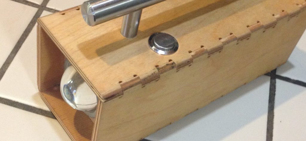
The original idea was to make a wide angle flashlight that my mother would use when she was out walking the dog. There are a lot of black aluminum tube flashlights out there that are very good but, most of them deal with a narrow beam.  I wanted something that was neither black nor aluminum nor a tube.  I was originally inspired by a youtube video:  How to make a 10W light at 12V from cheap parts Lots of experimenting happened from this starting point and it wasn’t that cheap by the time we got to the end.

Which lens to use and how to mount i t and what portable power system, where all questions that needed multiple attempts to arrive at a solution. In some ways this is an incomplete project, it still needs a better battery charging system than the one I

worked out. The wood case itself was CNC cut on the big router and then I manually rounded over the edges on the router table. I went with smaller finger joints and they came out well.  The cabinet pull for a handle gives it a sense of presense and mass that I try for in most of my designs.  I had hoped to get the flashlight ready for Christmas one year but it was pushed over five months until Mother’s Day the next. She does love it and all reports are that Dad “borrows” it often.