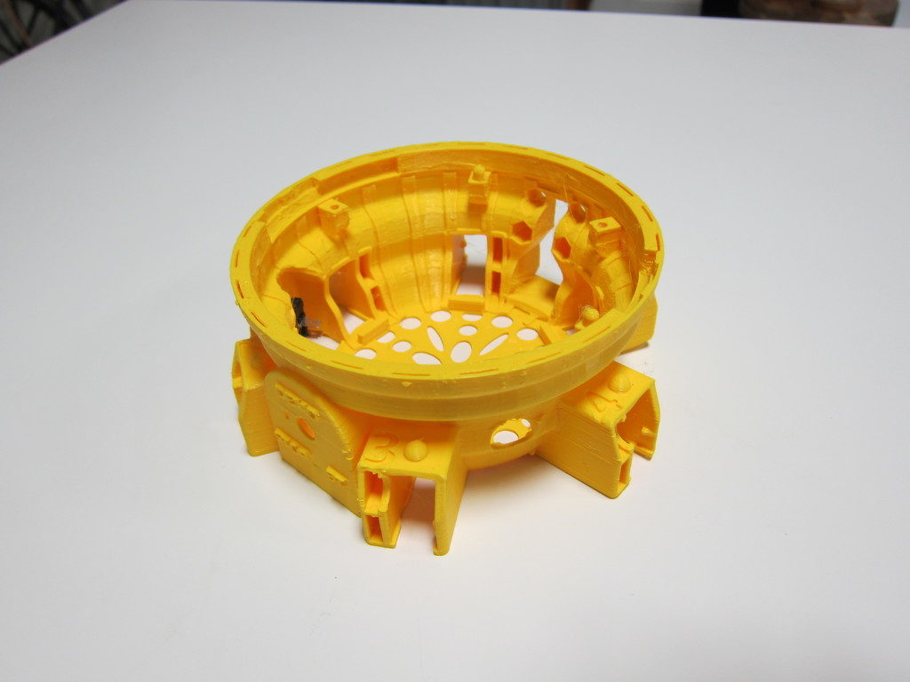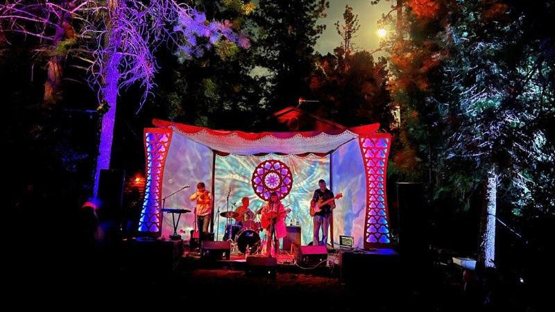
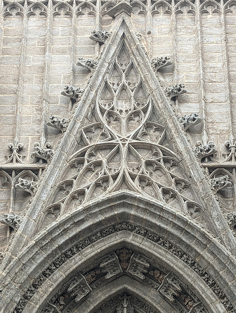
This summer, I had the opportunity to design and build one of the stages for a small annual festival. I’d just returned from a 3-week bike tour through Portugal and Southern Spain, where I’d seen an abundance of amazing historical buildings, from cathedrals to ancient fortresses.
Inspired by the amazingly elaborate details and layers of cultural influence in the architecture I’d seen, I wanted to create an intricate laser-cut plywood design that incorporated LED strips for nighttime stage lighting, but that still looked visually interesting during the daytime performances. It also had to be built ahead of time and easily assembled on-site.
I originally planned to use Rhino with Grasshopper for creating the design. Grasshopper provides a node-based way of scripting parametric models, and I’ve seen people make some incredible computational designs using it in combination with Rhino. Although I’d really like to learn how to use these programs, and they would have been a good fit for this project, due to time constraints, I stuck to the skills I already have from my background as a mechanical engineer. This meant using OnShape, an online Computer Aided Design (CAD) modeling program like SolidWorks or Autodesk Inventor.
To those unfamiliar with CAD tools that use parametric modeling, it works a bit differently than tools like Illustrator or Paint where you create the design directly. With parametric modeling, you define a series of geometric constraints, dimensions and formulas that define the shapes you’re trying to create.
Parametric models work a little bit like complex equations or a software code, in that it takes time to set them up, but once you do you can go back and adjust the inputs to get near-instant updates without having to recreate or manually tweak the design.
With parametric modeling, as when writing software, it’s good to follow the principle of, “DRY – Don’t Repeat Yourself.”
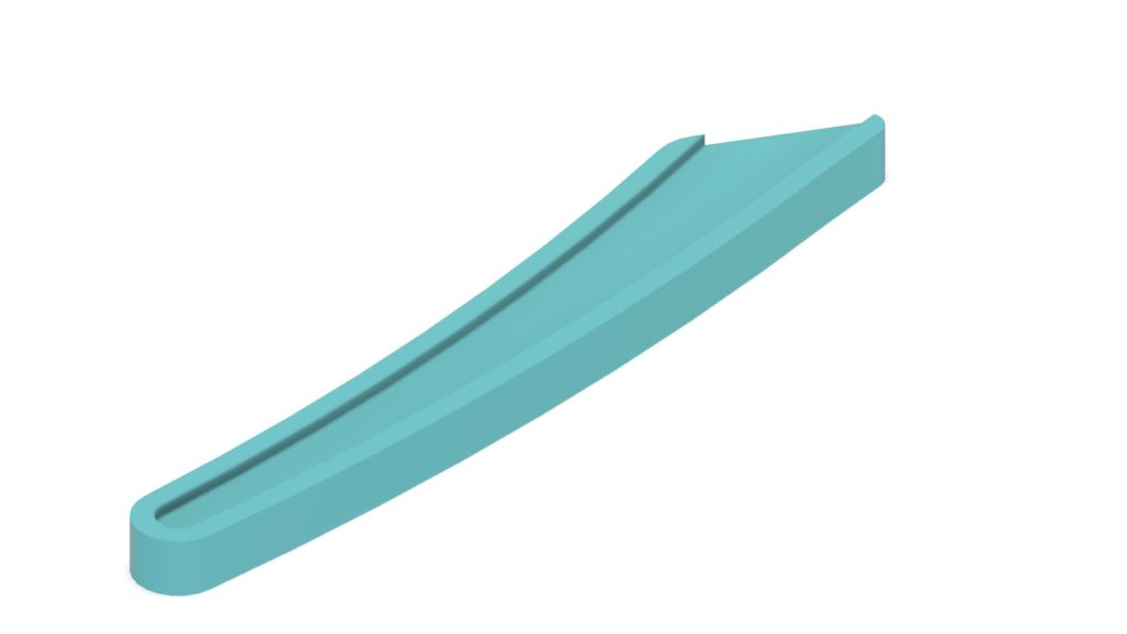
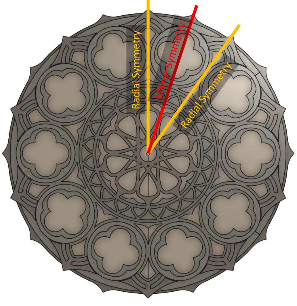
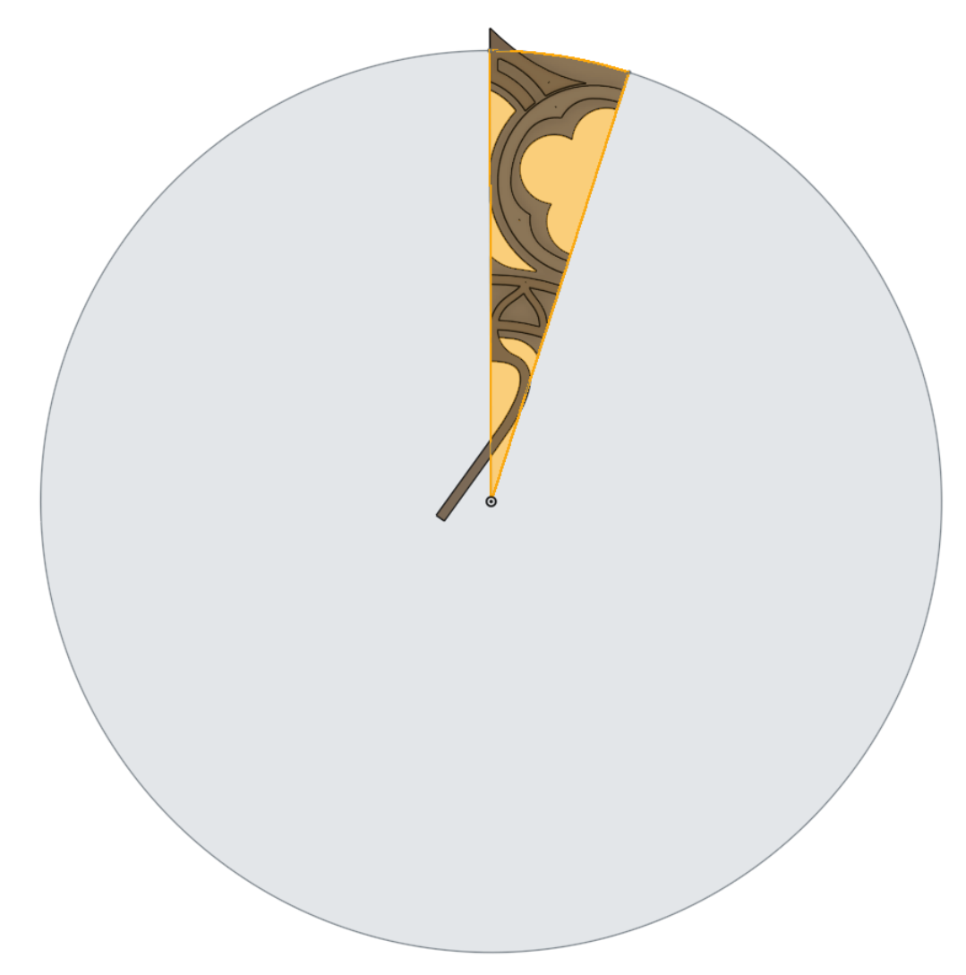
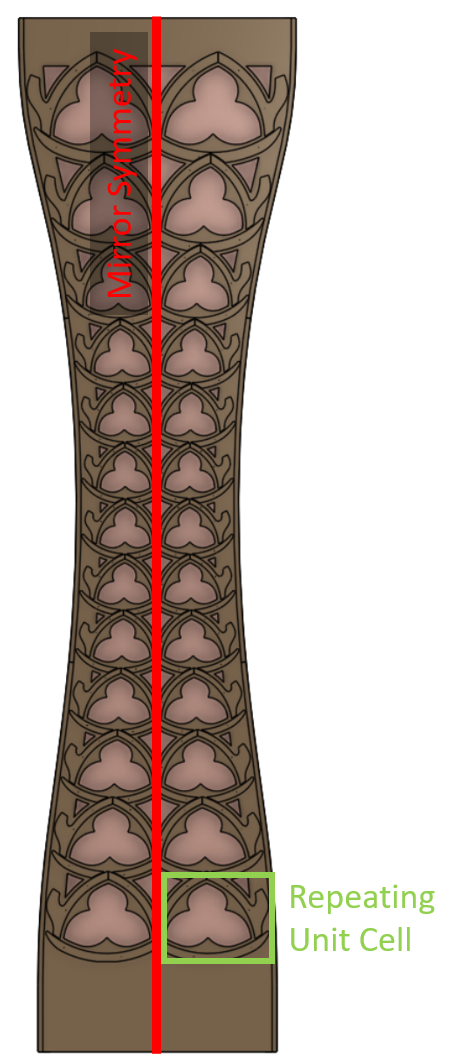
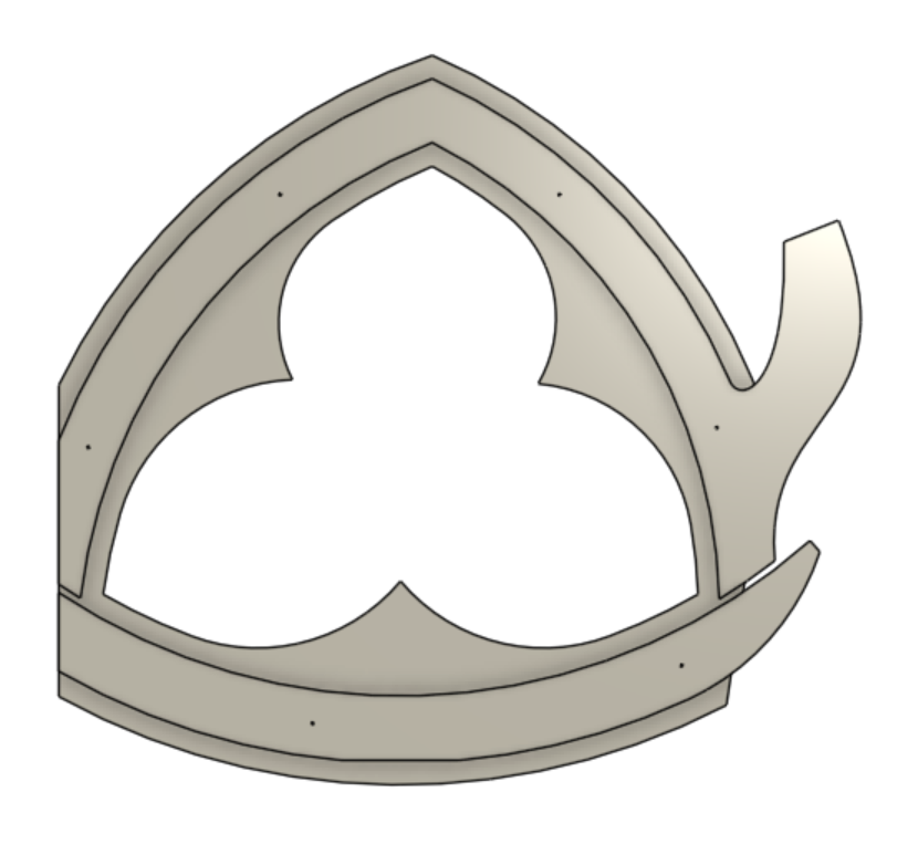
For the rose window element design, the first step was to look for any symmetries. In this case, it meant identifying the smallest “unit cell” that could be replicated to create the full design through mirroring, copying and patterning it. Fortunately every CAD tool has built-in commands to mirror and to rotationally pattern a part. These built-in commands make it easy to create the full piece from a smaller, simpler “unit cell,” while being able to update the original and see how it would look when patterned.
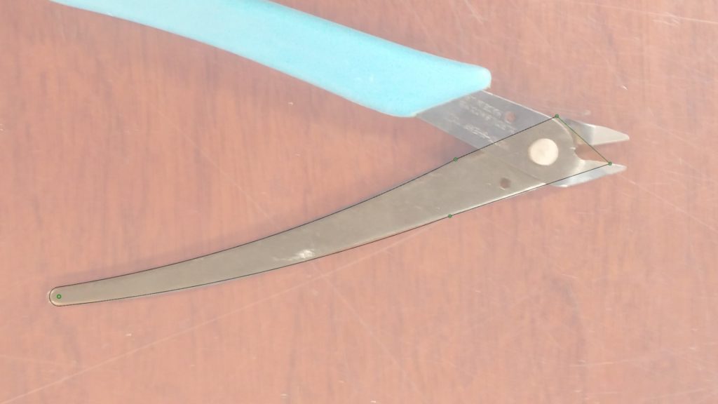
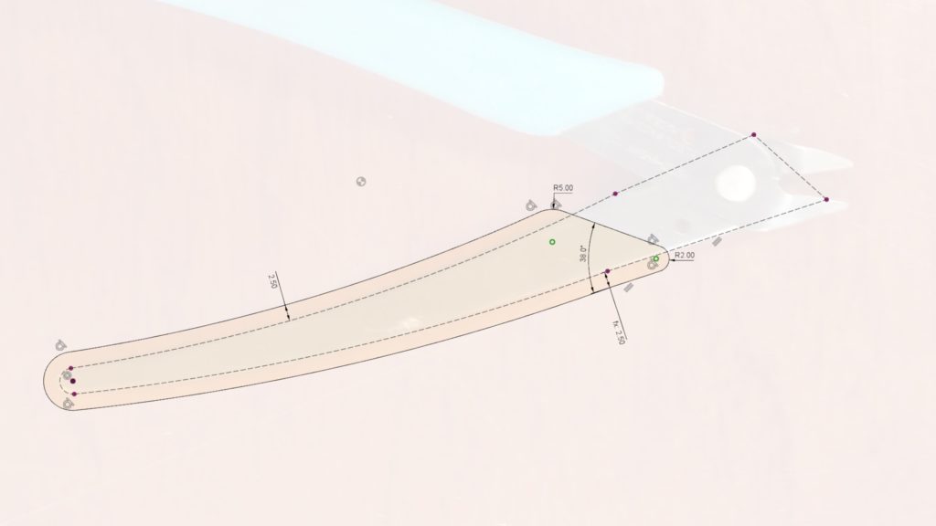
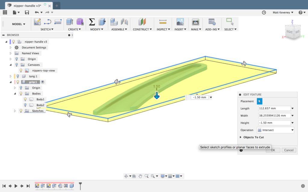
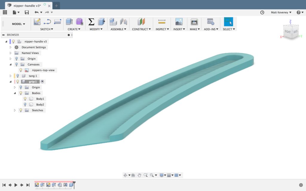
Creating a model for the pillars was more difficult. I wanted to be able to pattern a design along a gentle curve while having it adapt to the width between the curve and the centerline. There’s no built-in CAD command to pattern a part while changing the inputs that define the part (well, there is kind of but not in a way I was able to make work for this design). Instead, I set up a part for the pillar unit cell with different “configurations” where each configuration had the height and width of the bounding shape matching those measured along the curve. This was still a somewhat manual process because, if I changed the shape of the curve, I had to update the width and height of each part configuration to get it to match. That being said, with the curve fixed, I was able to change a single design and have all the instances of the unit cell update—my desired result. It’s worth noting that OnShape actually has its own scripting language, FeatureScript, which I could have used to write a custom command for the result I had hoped to achieve, but didn’t have the time. I plan to explore this approach more in the future.
All this modeling was to make the files required for the laser cutter, which reads 2D line drawings.
Someone who is proficient at a vector art tool like Illustrator likely could have created the same final design in 1/10th the time it took me to set up this complicated parametric CAD model. That being said, I had fun modeling it this way and I got more familiar with OnShape along the journey!
Once I was happy with the design (by which I mean out of time to continue tweaking it), I exported everything and headed to the laser cutter.
Laser cutting mostly went smoothly, although it took two passes to get all the way through the 1/4″ birch plywood. The main issue for the bigger parts was just getting the plywood to lay flat enough to keep the laser in-focus. I used every magnet in the drawer and could have used even more!
I hit a snag with the high-quality “Exterior Grade” Baltic Birch Plywood I had originally purchased for the project from MacBeath Hardwood. Whatever the manufacturer treated it with to make it exterior grade, prevented the laser from cutting past the first glue layer. After having made this expensive error, I bought the cheaper 4×8′ regular “White Birch” sheets from MacBeath, which they helped me rip into thirds that fit nicely into both the laser-cutter work area and the back of my car. The total cut time was approximately 200 minutes, spread out across several long, late-night sessions. It took far more time to layout and fixture the cuts than actual active cutting time.
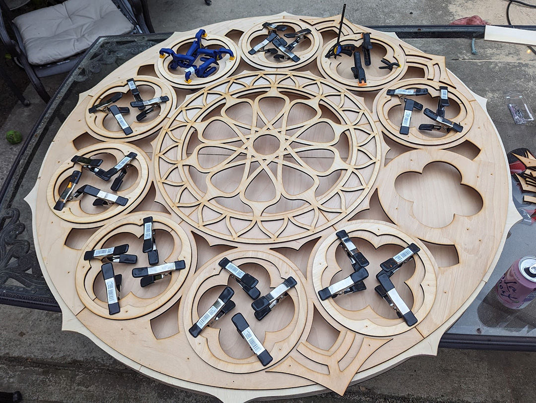
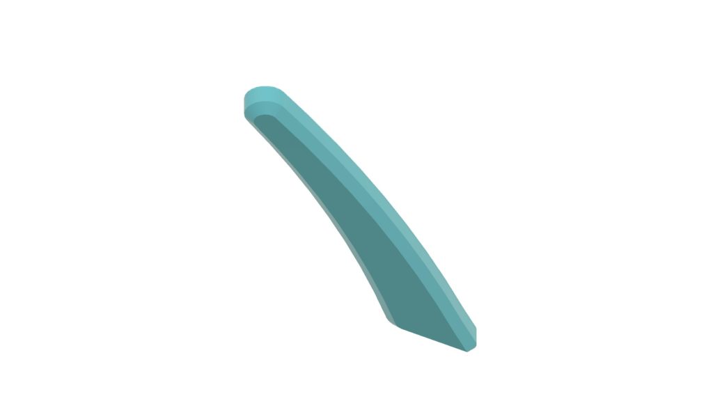
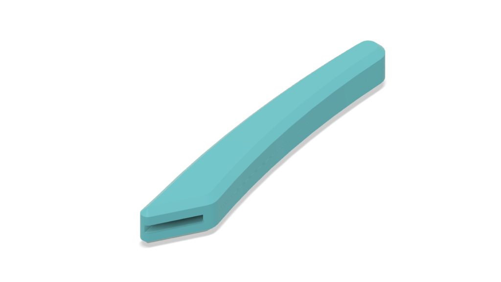
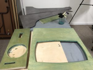
The final assembled pieces have a solid back spaced 1.5″ from the front cutout parts. I cut “rib” parts out of 3/4″ plywood and doubled them up to get the 1.5″ spacing. I then joined the parts with wood glue and a nail gun (the nails are invisible from far away and provided good clamping force while the wood glue dried). This resulted in surprisingly light and stiff parts.
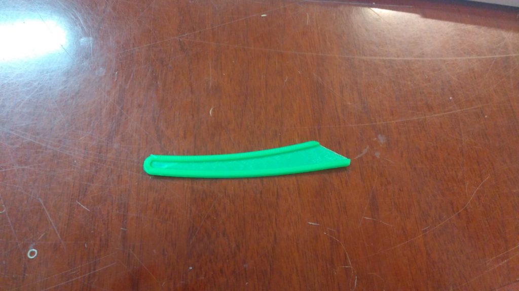
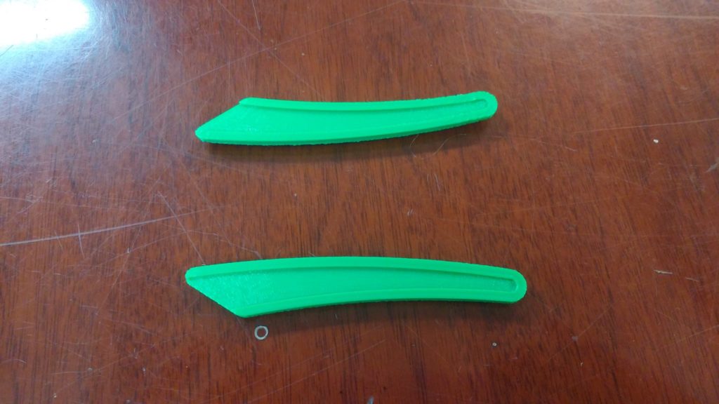
I created the detail on the front of the panels by gluing on smaller parts. This layup was challenging due to the sheer quantity of small parts.
For the pillars where the unit cell had many unique configurations, there were literally hundreds of small parts that all had to go in specific locations!
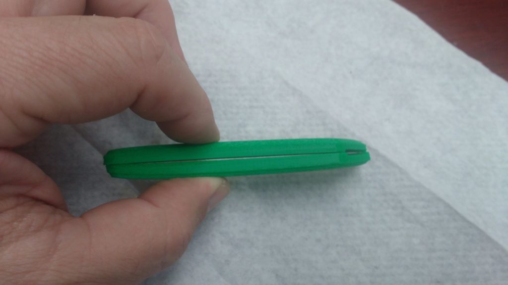
I added pre-fabricated holes to the laser-cut patterns for small brad nails which made it easy to align the small parts during assembly, and keep everything from sliding around during the glue-up. Once the glue was mostly dried I removed the brad nails so they wouldn’t become a permanent part of the assembly. The back panels are removable for installation and maintenance of LED strips glued along the inside face of the ribs. I used a silicone caulk for the LEDs, which works well as long as the ends of each LED strip are securely attached. The silicone caulk is strong enough to keep the strips in place, but easy to peel off if necessary.
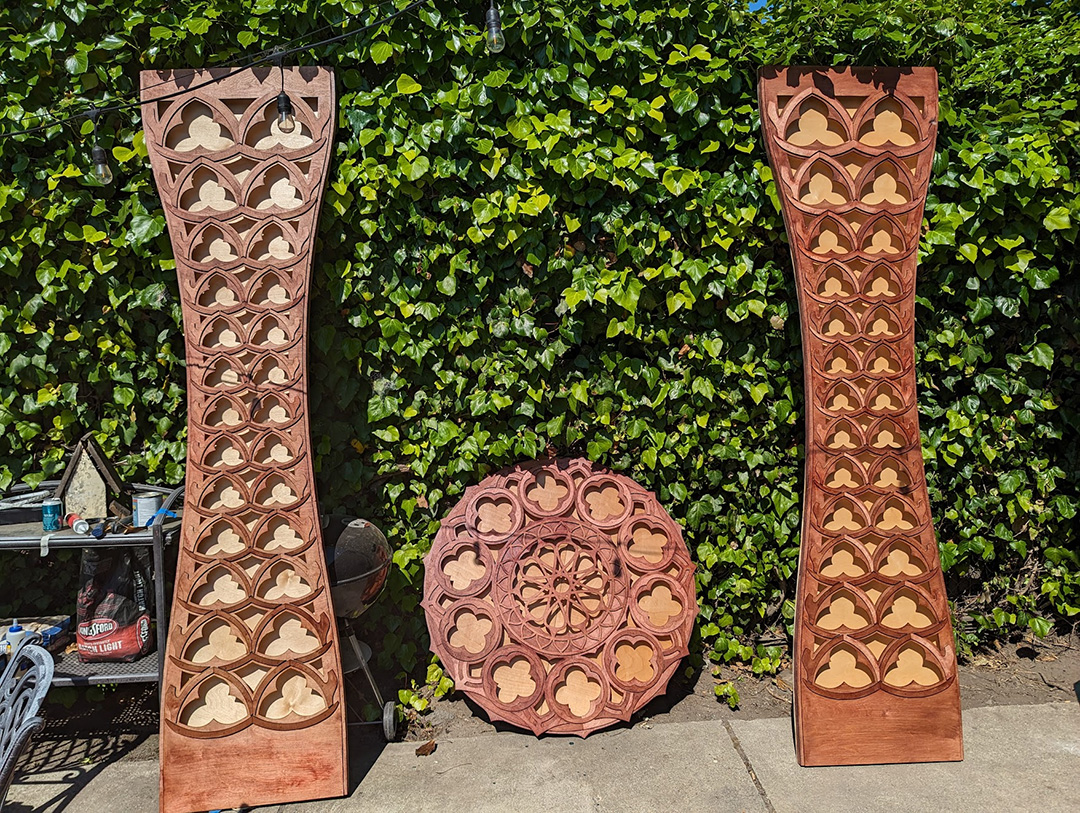
At the festival, the pieces were in the capable hands of Radiant Atmospheres, an event lighting collective practically next door to Ace. They hooked up the LED strips to a DMX decoder, which let them control them from the same system they were using to drive the rest of the stage lighting and effects. They also brought two rear projection units that set up an ever-shifting psychedelic pattern on the stage backdrop. I was really impressed with the work they did; it’s a bit hard to capture in photos but the stage lighting was gorgeous. All-in-all I’m pleased with how this project came out, and excited to take lessons learned and continue to play with the laser-cutter and other tools at Ace!

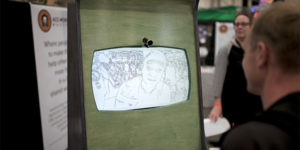
Oh, and the band in the cover image is the enchanting Foxtails Brigade!
What worked:
- The alignment holes and brad nails made the glue-up substantially easier; it would have been a real nightmare to get things lined up without them.
- In the design I left strategic gaps between parts to create the illusion that some parts were behind others, even though they were on the same layer. This visual trickery seemed to work; I had a few folks tell me they were surprised that it only had two layers.
- I loved the effect of the indirect LED lighting on the back panel, especially the regions lit by two different LED strips. It created smooth gradients that I thought were beautiful. The default with LED art is to create more complexity by adding an ever-increasing density of LEDs, but in this case I think less was more. It’s only five unique colors for all three of the panels, but the natural blending on the back panel made it seem more complex than it was. A happy accident of the constraints of the materials/budget I had to work with!
What could be improved:
- Creating the design out of hundreds of small parts made assembly incredibly time consuming. Designing for fewer, larger parts with more complexity per part would have cut down on the time it took to assemble everything.
- The ribs between the front and back layers were time consuming to make; I “scored” lines onto thick plywood with a light laser pass and then cut them out with a jigsaw at home. This took a long time and was difficult to do accurately, even with the precise guide lines created on the laser cutter. If I were certified on the CNC machine at Ace, that would have been a better way to go. Fortunately, the closest audience members were approximately 15′ away, and most of the mistakes were invisible from that distance.
- In hindsight, it would have been interesting to score inset lines from the edges of the parts on the laser-cutter; that would have been an easy way to suggest even more depth & visual interest.