Category: CNC Router

All things CNC Router Related

Pink plushy on CNC Router

Designing a CNC Program for Everyone

Smiling people at table with takeout and documents.
CNC Program planning in progress with Sharps(left) and Rachel (right).

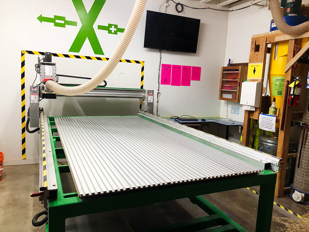
We love building kick-ass programs at Ace Makerspace, and this past year we had a special opportunity to apply our innovative, collaborative approach to program development to a much-needed community resource—our new Full Bed CNC Router. Like many small businesses, we took out an SBA Loan to survive the pandemic but also wanted to put some of the money towards mission-driven growth that would benefit the broader Oakland/East Bay community around us.

Did you know the Ace CNC router was the only public access router in the east bay not on a college campus? The community needs a more robust resource for people to use, run their small businesses, and gain job skills. It needs to be accessible for beginners and easier to maintain.

–Rachel Sadd, ED

We’d been thinking about investing in a new Full Bed CNC Router for our program since 2019, and after a few false starts over the years, we finally gained enough traction to bring our dream to life. Providing an approachable point of entry for folks of all skill levels to learn modern fabrication skills in the East Bay drove our subsequent program development process.

Green full bed CNC Router
Our new full bed CNC router, X axis mural, and workstation.

The new program we imagined would be:

  • Beginner-friendly
  • Affordable
  • Self-guided
  • Highly accessible

And would serve:

  • Folks interested in learning job skills
  • Small businesses
  • Folks making repairs
  • Hobbyists
  • Current and graduated students looking to continue their education and practice their skills
Smiling person with protective googles and carved wooden bat.
Student showing off their first CNC Project after class.

The Early Adopters

In order to build our dream CNC Program we put out a call for volunteers to join the Program Development team as Early Adopters.

We are seeking women, non-binary and BIPOC folks to join the CNC Early Adopter team. Ace firmly believes that a variety of lived experiences are needed to grow truly inclusive programs. And we are at a magic moment with the CNC Router Program as we re-design the program for the new router. You do NOT need to be an expert CNC Router Operator. The perspective of new users is also very valuable to program development.”

–Early Adopter Recruitment Post

For a truly accessible program we needed a group with diverse perspectives, skill levels, and lived experiences. We ended up recruiting:

  • Sylvia- A novice CNC operator with a technical background, who played an instrumental role in curriculum and knowledge check development
  • Bob- Someone with extensive CNC experience at Ace both as a user and an instructor
  • Frank- An advanced tool user with no previous CNC experience and an old school approach to documentation
  • Dave- Someone with CNC experience in both Ace and outside contexts
  • Sharps- A former tool manager for a shared shop with extensive CNC experience outside of Ace
  • Liz- Ops manager in charge of the executing the environmental design for the physical space and limited CNC experience
  • Rob- A technical contractor who helped build out the space and design the X and Y axis murals
  • Rachel- Executive director of Ace Makerspace
CNC Router in action
Taking the new CNC Router for a test drive shortly after delivery. Part of developing a new program involves testing the machine in a variety of ways and troubleshooting issues.
Checking the X and Y axes for precision after troubleshooting an early issue with router bed alignment.

Building a Beginner Friendly Program

Building an approachable CNC program requires bridging the gap between the advanced user approach and a more equitable, beginner-friendly approach.

X, Y Axis Murals
X and Y Axis Murals for easy reference make our newly designed space approachable for novice CNC Operators.

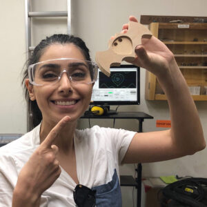
Sylvia, a novice CNC Operator with extensive technical writing experience, played a major role in developing the curriculum and writing the knowledge check. Ace Communications Associate, Jacky, sat down with Sylvia to learn a little bit about her perspective as a novice CNC operator on the team and what beginners can expect from the new program.

1. What prompted you to join the Early Adopters Team?

I joined because the call was for a BIPOC beginner and that was me.

2. What was your experience as a beginner CNC Operator working on curriculum development?

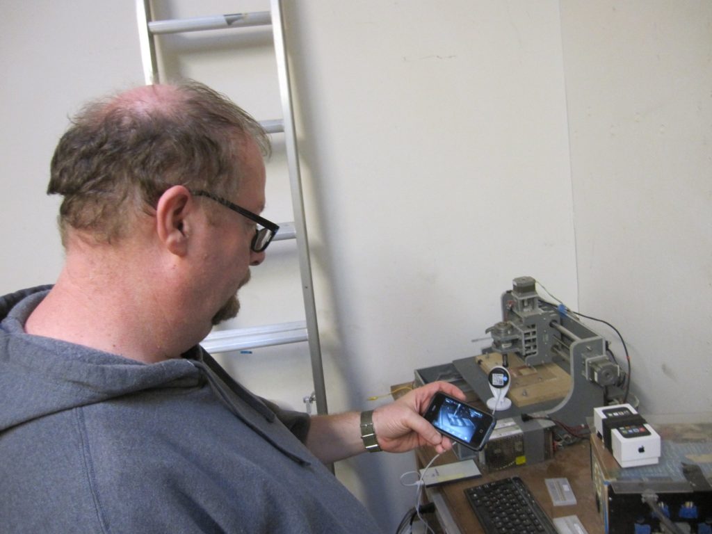
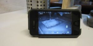
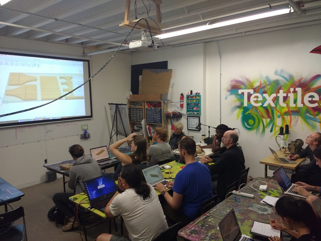
My first experience with CNC Routing was with the Forest Scientific trainer who came to Ace to work with the Early Adopters. That training session, which lacked visual aids and handouts, wasn’t helpful to me as a beginner, although it did seem to resonate with the more experienced users and did take a hands-on approach.

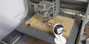
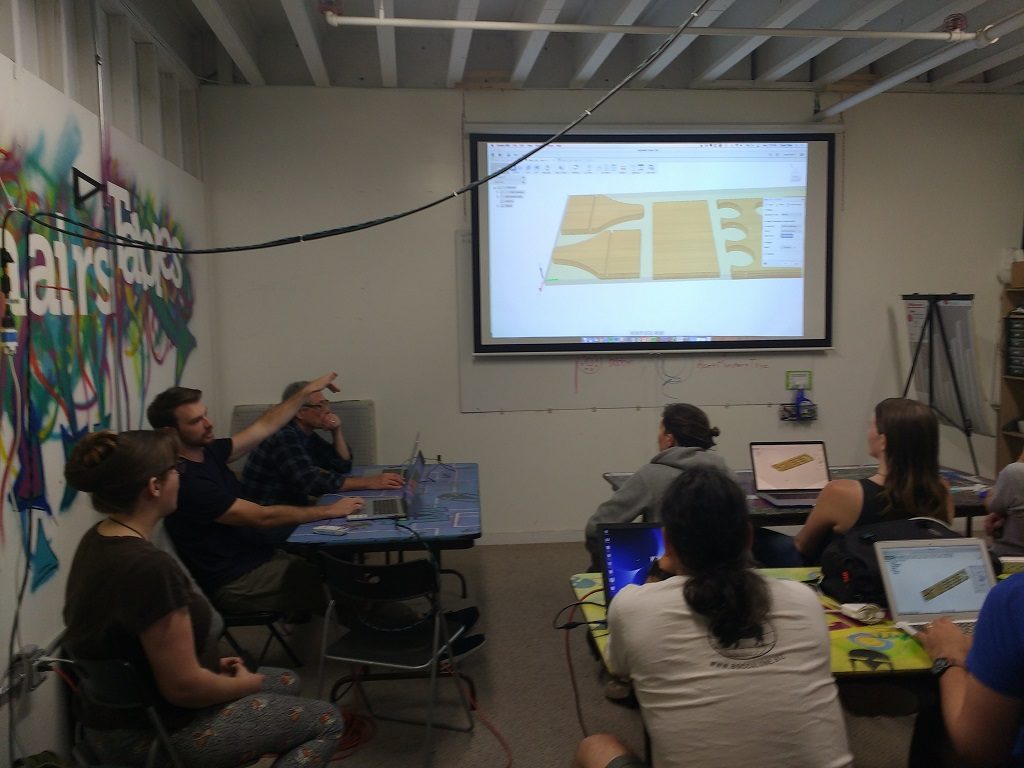
Writing the curriculum was a highly iterative process, and as a beginner I was still able to contribute at our first team meeting by simply asking questions. Rachel provided background on Ace culture with respect to collaborative class development. Sharps wrote an initial draft outline covering CNC Router concepts. Bob contributed his expertise from years of teaching beginner CNC users. Frank [another New CNC Operator] documented the step-by-step process of operating the CNC router. During team revisions Frank and I identified things that were unclear to us as beginners. For example, the Router has 3 axes: X and Y and Z axis, and one of the training slide examples mentioned ‘2.5 axis.’ A beginner wouldn’t be able to decode that.

3. What is one (or more) thing you really thought about/kept in mind as you were contributing to the writing of the CNC knowledge check?

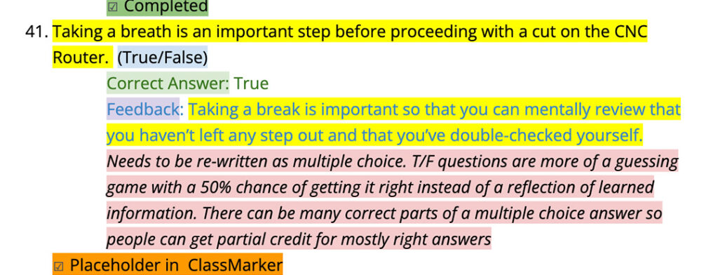
The more brains that attack this the better. I thought the team effort was key, which included leveraging the Laser Team’s tried and tested Laser Knowledge Check as a starting point. Sharps and I generated an initial draft of questions. Then there was a technical review by Bob and Sharps, an inclusivity review by Rachel, a re-write by Rob to transition questions from a true/false format to a multiple choice format, and a review by Jesse M who provided valuable feedback from a test taker perspective.

Color-coded Knowledge Check revisions.
Revising the new CNC Knowledge Check as a team.

4. What did you learn through the process?

How important it is to address different kinds of learning styles. Some folks are visual, some folks like a checklist, and some folks need things said aloud, while other folks need to touch the machine for the info to take hold.

5. What can beginners expect from the new program?

“An evolving process that they can contribute to in order to make it even better!”
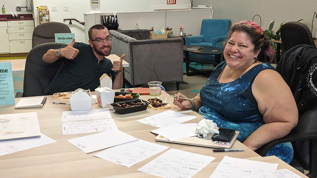
Pilot Classes Begin

CNC carved wooden bat coaster
Wooden bat coaster practice project for New CNC Router Basics Workshop.

Ace is looking for 4 beginners for the next CNC Pilot Class! It will likely be mid-month and definitely on a weekend. Reply to this thread if you are interested. Update: Please if you have previous CNC experience do not put yourself on the list.

-Pilot Class Announcement

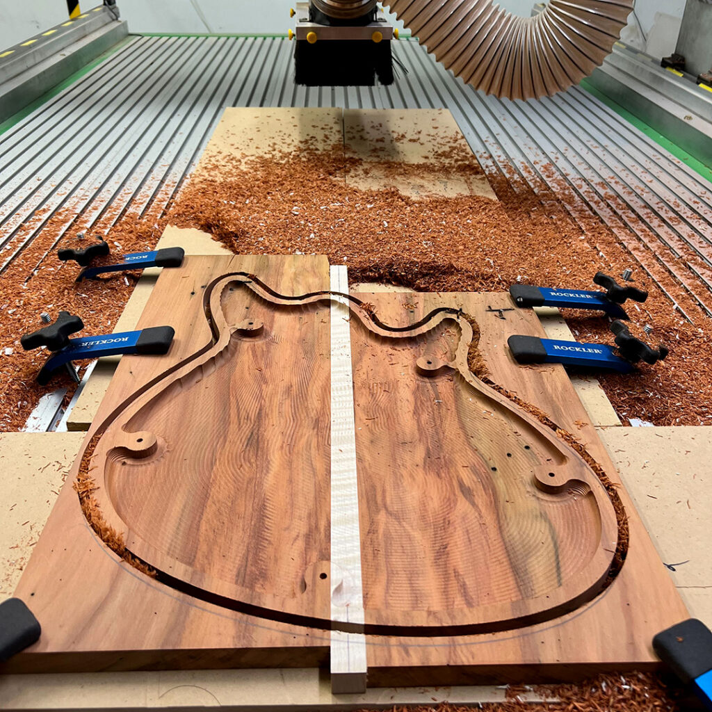
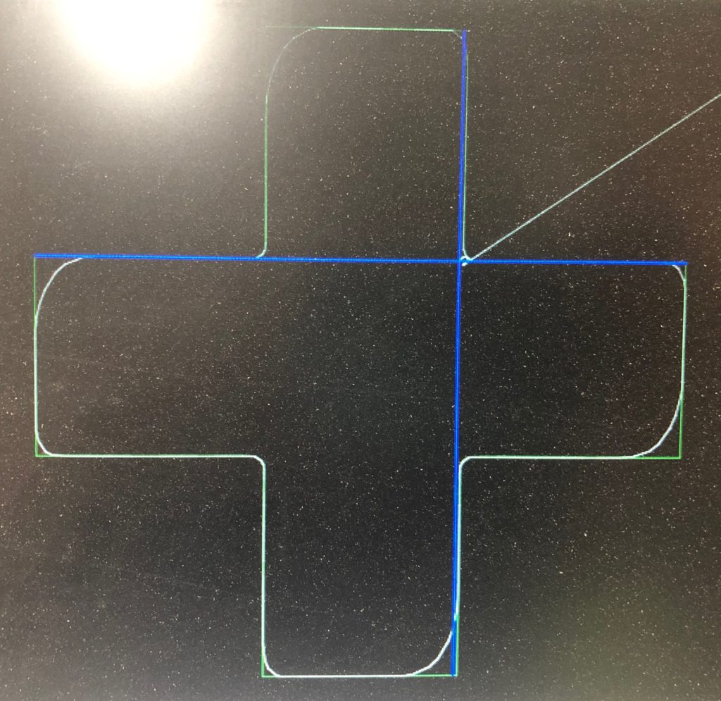
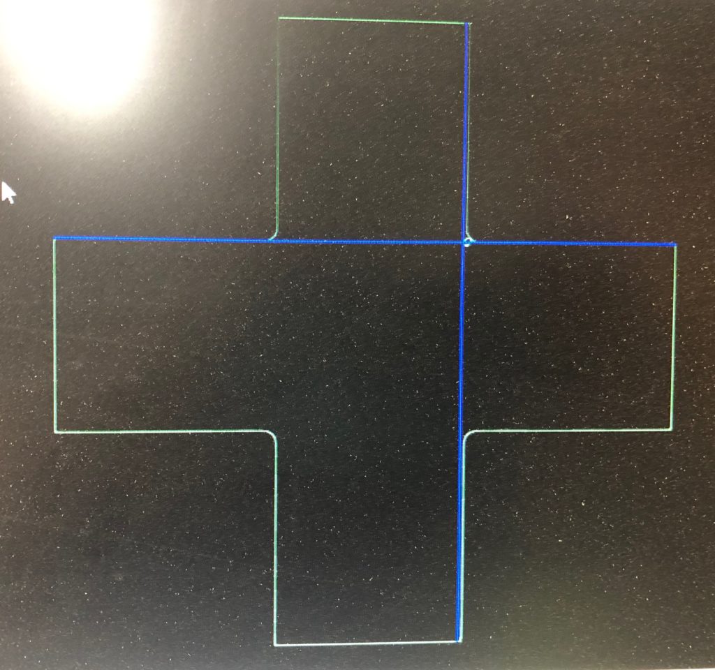
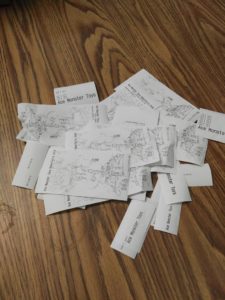
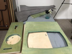
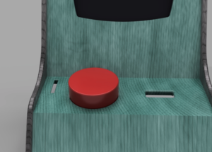
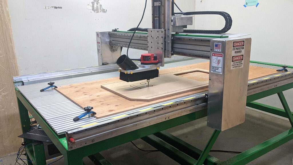
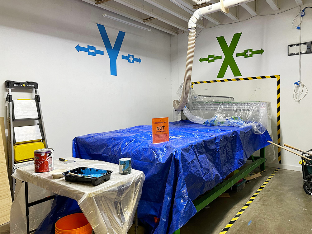
Finally, after installing the New Router, learning how to use the new machine and experimenting with it, designing the curriculum, handouts, knowledge check, and other user documentation on the Ace Wiki, installing a new desk, painting X and Y Axis murals for easy reference, and designing a beginner friendly “data pack”, it was time to pilot the new CNC Basics and Certification class starting with….beginners!

What’s next for the CNC Router Program?

Our program is evolving and we plan to continue iterating our collaborative approach to design as we fine tune our existing CNC Router offerings, grow our program, and develop more great beginner-friendly learning opportunities for our East Bay community.

Here’s a taste of what to look forward to as we continue developing new learning opportunities for CNC Routing at Ace:

  • Software Design Classes for CNC Routing
    • V-Carve Design for CNC Routing (less powerful, but less complicated)
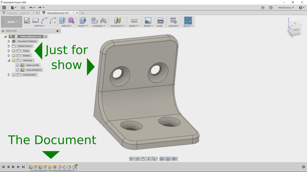
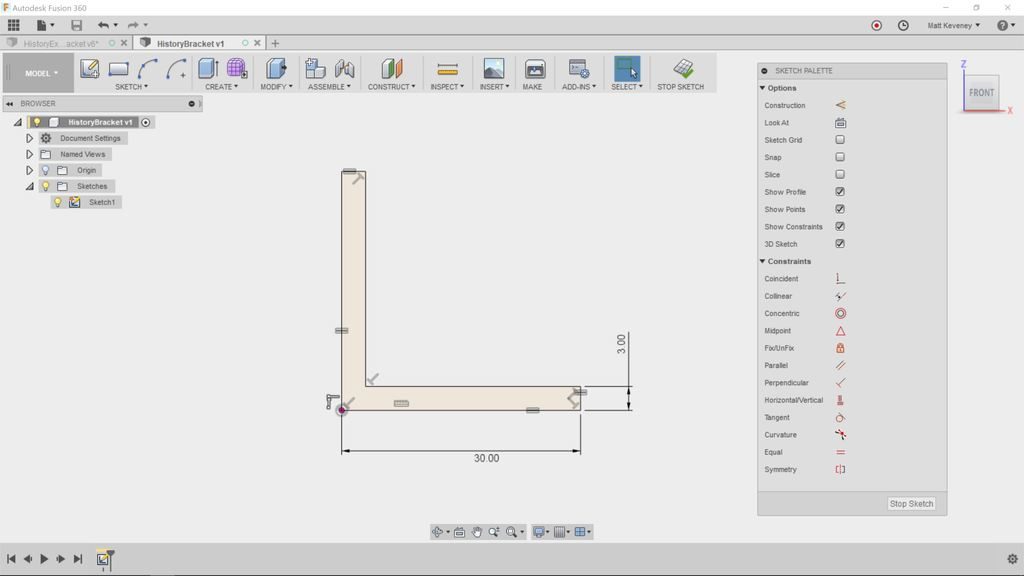
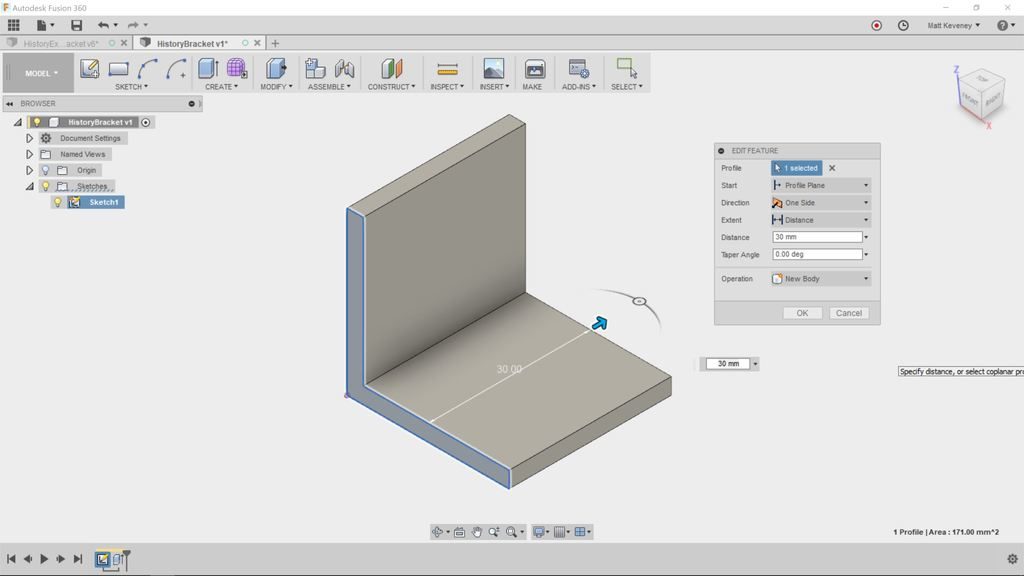
    • Fusion 360º Design for CNC Routing (more powerful, but more complicated)
  • CNC Router Advanced Operation and Certification Workshop focused on 3D Routing and handling specialty materials (like plastic) safely
  • Open Labs with focused topics like “planing contours” and “cutting plastics”
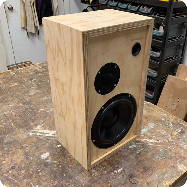
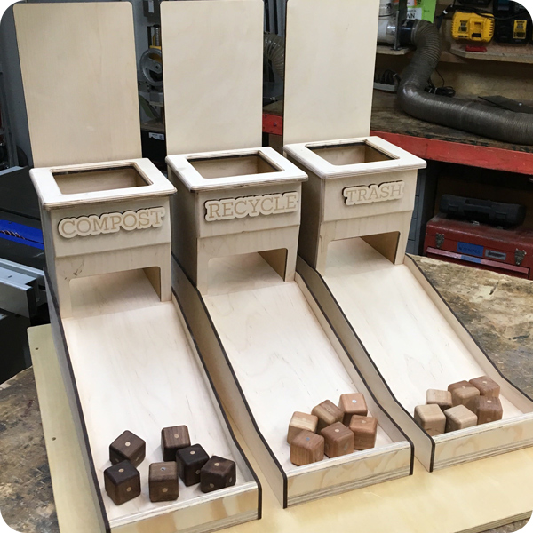
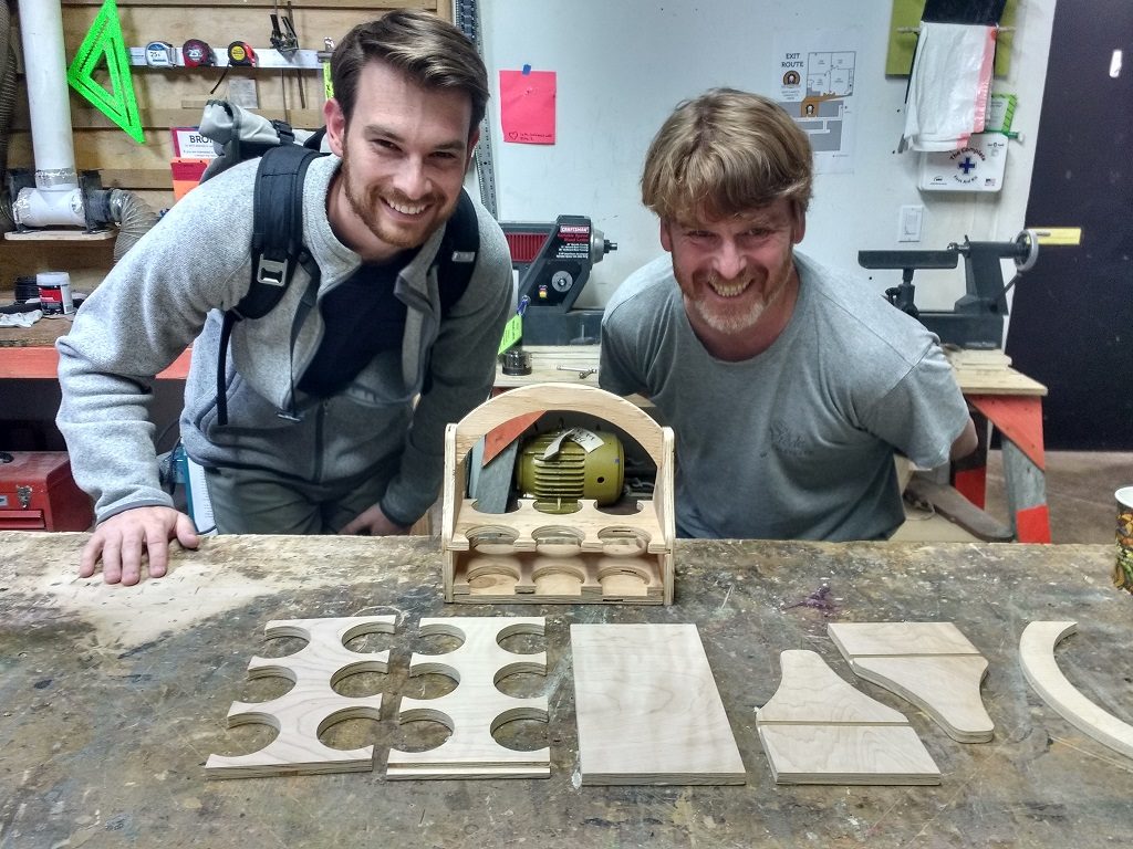
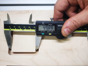
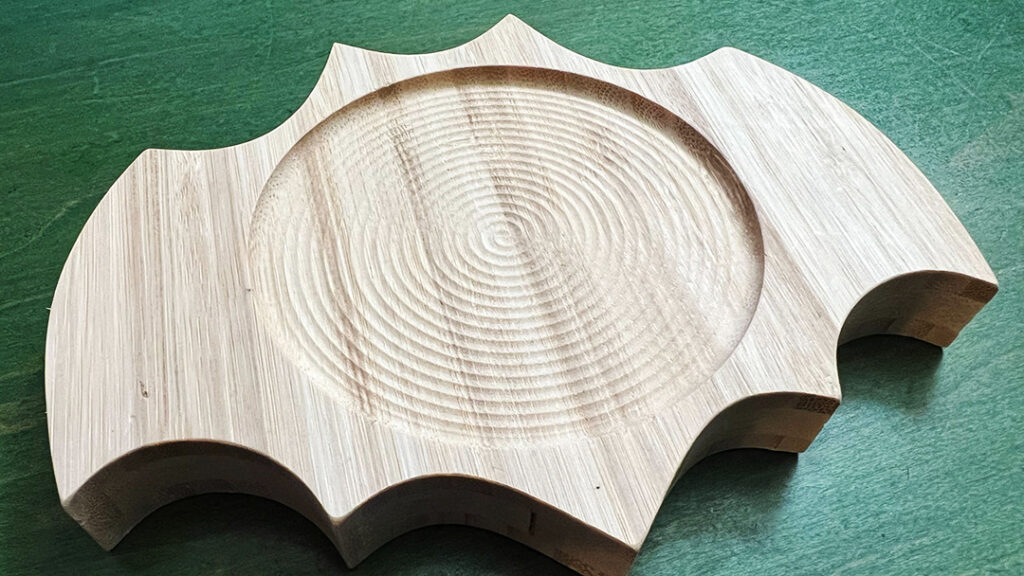
  • Practice Projects like dice trays, bee-houses, and clocks

In order to create robust and equitable resources, we invite folks interested in being a part of this exciting process to bring their unique perspectives, skills, and talents to the table. We also plan to continue working side by side with our community as we evolve other current and future programs.

Guitar body on router bed
Guitar in-progress on new CNC Router Bed.

Made at AMT-June 2019

NOMCOM Fob All The Things dashboard | AMT Software • Bodie/Crafty
Hand Built Speaker | Workshop • David
Recycling Game | Workshop/Laser • Bernard M.
Solid wood credenza | Workshop | Raj J.
Tiny electronic brass jewelry | Electronics | Ray A.
RFID Mint Dispensing Box | Laser+Electronics | Crafty
Wood Signage | CNC Router | James L.
Fabric Kraken stuffed with 720 LEDs | Textiles + Electronics | Crafty

Fixing the CNC’s rounding of corners.

There have been some troubles with the CNC not following Gcode paths exactly and rounding corners.

In this first picture of the Mach4 screen you can see the green lines which are the path the CNC should follow, and the white lines which are the path the CNC actually followed. (ignore the blue lines)

The problem is the CNC is rounding over the outer corners. This is a result of the CNC trying to move faster than it can manage. The max speed of our CNC is 200 inches per minute. In the above picture it is trying to cut at 150 IPM and can not handle that speed on the corners so it rounds them, which can ruin the piece. Even though the CNC can go faster in a straight line it can’t change directions that fast.

The solution is to use a slower feed rate. But this can greatly increase cut times and other issues such as tool dulling and excess heat.

Fusion360 has a solution called “Feed Optimization”. What it will do is reduce the speed in just the corners to 25% of the feed rate. In this example it reduces the corner feed speed to 37.5 IPM.

In this next picture you can see the white line of the actual cut path looks identical to the green Gcode path with Feed Optimization turned on.

The Feed Optimization setting is found on the 4th tab (labelled Passes) of the Operations Dialog when you are in the Manufacture workspace.

In the bottom of this picture you can see the checkbox to turn it on. The defaults should be fine and will reduce your corner speeds to 25%. This only adds a small amount of extra time to the cut.

This project was set to 100 inches per minute so Feed Optimization reduced the corner speed to 25 IPM.

Mouse over each setting for an explanation of what it controls if you would like to fine tune even more from the defaults.

Adventures on the Axis of X and Y

The following is the story of one dedicated AMT members adventures in caring for our beloved hacked CNC Router.

When I previously measured the steps on the x-axis, I found a big step difference between the forward and the backward motion. I decided to remove the x-axis to see if there were any mechanical reason which might affect this. At the same time, I removed the z-axis to see if there might be a mechanical reason for the occasional dropping of the z-axis.

z-axis

I removed both z-axes from the CNC and checked the Porter-Cable axis for wear. In addition, I checked to see if there was any slippage between shafts and timing gears, as well as between the shaft and the coupler. (This was a suggestion from @drshiny.) To me, the z-axis looks in a good condition. I identified two issues, one was the timing belt and the other was that the guide wheels were not running tightly on the Guide rails.

The teeth of the timing gear were clogged with debris which looked like it had come from the timing belt. The only picture I have was taken after cleaning, but before doing that, I found a surprising amount of black stuff which was compacted into the grooves. I swapped the belt with the one from the Perske spindle which I assume has not done the same amount of work.

The groove in the bottom of the guide wheels was filled with compacted debris which caused the wheels to not run tightly on the guide rails. The point of the rail sits within the groove of the guide roller. If there is debris within the groove, the guide sits only on the upper face of the guide wheels as shown on the left-hand picture as opposed to the right-hand one(you may need to enlarge the picture to see it).


I used WD40 to softened the debris, and then used the edge of a chisel to scrape the stuff away. It was necessary to repeat this process several times for each wheel.

x-axis

After removing both of the z-axes and the timing belt on the x-axis, I discovered that the x carriage was running only against the back two guide rollers(or wheels), with daylight showing between the front guide roller and guide rails. As before I cleaned and scraped the guide rollers and after tightening the two adjustable back rollers, I tested the smoothness of the carriage by pushing the x-axis forward and backward by hand along the path. At this point, the carriage was running smoothly. When I tested the number of steps forward and backward, I found there was no longer such a big discrepancy, which was the reason I decided to remove the z-and the x-axis in the first place.

y-axis

We know the rack and pinion on the left-hand side has much higher wear than on the right-hand side. I think this is due to the two carriages on the y-axis not running parallel. There are 2 types of guide wheels, fixed and eccentric which means they are adjustable. 2 fixed wheels go on one side and the other 2 go on the other side. I wonder if one of the wheels has been swapped around. That would lead to the carriage being at an angle once tightened. Steve looked at this and also said that the pinion runs at the bottom of the rack and needed to be lifted. It is possible that once the guide wheel has been cleaned and adjusted, it may be enough to lift the rack higher without having to resort to further shimming. This work has not been done yet.

AMT’s Adventures at Maker Faire 2018

The Art Printing Photobooth aka The Edgy Printacular

At the Bay Area Maker Faire 2018, a team of Ace Monster Toys members created a photobooth where participants could take selfies which were then transformed into line art versions and printed, all initiated by pressing one ‘too-big-to-believe’ red button.

Back in March, AMT folks began prepping for Maker Faire 2018, and had an idea: what if you made a machine that could take a selfie and then generate a line art version of the said selfie, that could then be printed out for participants like you and me?! Thus, the Art Printing Photobooth was born! This project was based on the Edgy Cam project by Ray Alderman. AMT created a special slack channel just for Bay Area Maker Faire 2018 #maker-faire-2018. Then members set about figuring out how exactly to make this art-generating-automaton and Rachel (Crafty) campaigned for having a ‘too-big-to-believe’ push button. They would need many maker skills: CNC routing and file design, woodworking, electronics wiring, and someone to art it all up on the physical piece itself. Bob (Damp Rabbit) quickly volunteered to take on the design and CNC cutting, while Ray (whamodyne) started to chip away at the code that would be used to convert photos to line art.


Then the trouble began. By mid-April, our intrepid troubleshooters were running into all sorts of snags – so much so that the original code needed to be thrown out and rewritten from the ground up! To add additional difficulty (and awesomeness!) the team decided to use a Print on Demand(POD) service to allow participants to have their generated art uploaded and available to be printed on mugs, t-shirts, posters, etc. Soon after, Ray wrote up a new digispark code for the big-red-button to actuate the script and convert and print the line art (code given below) using Python3, opencv library, printer library from https://github.com/python-escpos/python-escpos.


Meanwhile, Crafty Rachel and Bernard were configuring the TV mount that would be the selfie-display of the photobooth and Damp Rabbit was busy CNCing and painting up a storm to create the beautiful finished product – The Edgy Printacular! The EP was a hit and won three blue ribbons at Maker Faire 2018. Another happy ending that speaks to what a few creative makers can do when they put their heads together in a place with all the right equipment, Ace Monster Toys <3

Big empty room

AMT Expansion 2018

This month AMT turns 8 years old and we are growing! We have rented an additional 1200sqft suite in the building. We have a Work Party Weekend planned June 1-3 to upgrade and reconfigure all of AMT. All the key areas at AMT are getting an upgrade :

CoWorking and Classroom are moving in to the new suite. Rad wifi, chill space away from the big machines, and core office amenities are planned for CoWorking. The new Classroom will be reconfigurable and have double the capacity.

Textiles is moving upstairs into the light. The room will now be a clean fabrication hub with Electronics and 3D Printing both expanding into the space made available. Photo printing may or may not stay upstairs — plans are still forming up.

Metal working, bike parking, and new storage including the old lockers will be moving into the old classroom. But before they move in the room is getting a face lift by returning to the cement floors and the walls will get a new coat of paint.

The CNC room and workshop will then be reconfigured to take advantage of the space Metal vacated. We aren’t sure what that is going to look like beyond more workspace and possibly affordable storage for larger short term projects.

Town Hall Meeting May 17th • 7:30PM • Plan the New Space

What expansion means to membership

The other thing that happened in May is after 8 years our rent finally went up. It is still affordable enough that we get to expand. Expansion also means increasing membership volume to cover the new rents and to take advantage of all the upgrades. We are looking to add another 30 members by winter.  Our total capacity before we hit the cap will be 200 members. We feel that offering more classes and the best bargain in co-working will allow us to do this. Please help get the word out!

The New Suite in the Raw

Big empty room

Fusion 360 Hangout at AMT

December 7th we started a new meet up for Fusion 360.

The group brainstormed on tool-path creation and resolved to develop an understanding of multi-stage CAM processes that can be used on the various mills, routers and cutters at AMT.

We had a terrific time at the hangout. Matt our 3D Printing steward and five others attended. All were quite experienced Fusion 360 users, in contrast to most of the previous Fusion meetings which tend to be weighted toward newcomers. I think everyone present was a AMT member.

We opted to pass the projector cord around and look at all of our projects as a group. Another approach might be to break off into twos or threes; maybe we’ll try it that way next time.

  • Bob showed us some renderings of cool guitar designs he’s been working on.
  • Rachel (aka Dr. Shiney) showed us a guitar body a client of hers needed cut; we struggled together for a while trying to figure out Fusion’s 3D tool-path generation. I think something like this would be a great thing to get Taylor’s input on: A multi-stage CAM process including facing, profiling, and 3D carving.
  • Emory gave us a quick look at his own CAM project, which involved re-mounting the workpiece to cut both sides: tricky stuff.
  • Chelsea showed us her silicone casting project. She’s come up with a pretty elaborate flask and core to be 3D printed. We’re all anxious to see the results, but those are going to be some long prints! I recommended smaller test pieces to get sizes and clearances right and generally experiment with the process before committing to the final design.
  • Matt brought along a bunch of finished projects you’ve probably seen before if you’re a regular at our Thursday meetings; nothing new, but all done in Fusion 360.


History editing in Fusion 360

The 3D View is “Just for Show”

With most editing tools, the document you’re editing is comprised of the things displayed right in front of you. With a word processor, it’s the words; a spreadsheet, it’s the numbers and formulae; an image editor, it’s the pixels. This is also true of mesh-centric 3D modelers like Blender or SketchUp. When you move edges or faces, bore holes, or perform any other operation, you’re modifying the Mesh: a collection of points, edges and faces in Cartesian 3D space. The mesh itself is the document.

But with Fusion 360, the document is composed of the sequence of things in the history timeline (shown at the bottom of the screen). The 3D view in the center of the screen is the result of executing that sequence of operations. The things in the Browser (the hierarchical object list on the left), are also a product of the history timeline sequence. Think of the timeline as the program code that produces your design. As far as editing is concerned, the Browser and 3D view are just for show!

I’ve always thought that ‘history timeline’ was a misleading name. ‘Operation Sequence’ might be better. In real life we can’t yet travel back in time, so the term ‘history’ suggests that it’s merely an informational record of what already happened. Not so! Items in Fusion 360’s history timeline can be rearranged and edited. Learning how to do so is key to getting the most out of the tool.

To get some practice with the timeline, let’s walk though a (somewhat contrived) example: The corner bracket pictured above.

First create a sketch describing the basic cross section profile.

Then extrude with the push-pull tool to create a solid body.

Now create a sketch on one of the sides to describe mounting hole profiles.

And extrude to bore the holes.

Now, we’ll use some of the modify tools. First, add a large fillet to strengthen the bracket.

Add a chamfer to counter-sink the holes.

A fillet to round over the top corner.

Add another for the other top corner.

Add one more small fillet to break the sharp edges.

Well, it clearly needs some work, but let’s review the timeline to see what we’ve done so far. First, make the sketches visible for clarity’s sake (find the sketches in The browser and click the light bulbs). Then click the home and fit buttons to get this view:

Right click the first item in the history (a sketch) and select Roll history marker here. The body will vanish from the 3D view, and the Browser will display just one object; the sketch. Don’t panic; you haven’t deleted anything! Note that the items in the history are still there; they’re just grayed-out.

You’ve moved the history marker to display the model as it was defined at this point. Remember: the history timeline is your document; the 3D view and Browser are just for show.

Click the next step icon to advance the history marker. With each click, the display will update to reflect another operation. When you reach the end the 3D view will reflect the model as defined so far.

We can give the sketches and features more meaningful names. This is a good practice in any case, but is especially useful when getting familar with the history timeline.

Right click each item in the timeline; click rename and enter the following names:

basic profile
basic body
hole definitions
holes
strengthening fillet
countersinks
corner roundover
corner roundover 2
break sharp edges

To see the names you’ve just entered, hover the mouse over each item in the timeline. The names for sketches also appear in the Browser.

While labeling our history items (sketches and features), I remembered that we rounded the outer corners with two seperate features. It makes more sense to use a single feature, since both of these fillets should always be the same size. That way, if we ever want to change the size we need only edit one feature.

Right click the corner roundover 2 feature and delete it. Fusion will warn that the feature is referenced by other features in the timeline. Click Delete anyway!

Now the break sharp edges round-over feature has a yellow background, indicating that something is amiss. Ignore this for now, we’ll come back to it.

Right click the corner roundover fillet and select edit feature (or just doubleclick the feature’s icon). The fillet dialog will be shown, and the 3D view/browser will reflect the model as it was defined at that point in the history.

The fillet dialog indicates that a single edge has been selected. Hold shift and select the other upper edge. Then release shift and click OK.

Notice that the break sharp edges round-over hasn’t been applied to this new fillet. This is due to the same issue that arose when we deleted the corner roundover 2 feature.

So, let’s have a look. First, right click and choose review warning. This displays more detail about what went wrong. In this case it says: “The edge reference is lost, try editing this feature to reselect the lost edge.”

So, let’s try editing as suggested. Double-click the feature to edit.

Even though the model has the same shape as before, the underlying edges that define the body have changed due to our upstream edit. Notice that it now says two edges were selected (originally there was just one chain of edges). If you press shift these edges will be highlighted. You can clearly see a gap where the redefined fillet is.

Click the ‘X’ next to edges in the dialog box to deselect the edges; then reselect the edge. It will select the entire edge chain again. Once saved, the yellow warning background will disappear.  Be sure to address all warning issues in your timeline! If ignored, they’ll just cause trouble later.

When editing something in the history, we often have to review and adjust downstream features like this. This can be very frustrating if you aren’t familiar with the timeline. With a little practice it becomes second nature, and is a worthwhile skill to attain sooner rather than later.

So, let’s finish our bracket. We need holes and round-overs on the other tab, and our break edges fillet needs to go around the entire perimeter.

We’d like the hole pattern to be identical on both tabs of the bracket. We could duplicate the sketch and extrude operations that we used on the first tab, but if we ever changed the pattern (maybe to use more holes), we’d have to edit two sketches instead of one, and we’d have to be careful to keep them identical. By using a mirror operation instead, we can use a single hole definition, making for simpler adjustments later.

First we need a reflecting plane. Choose Construct/Plane at angle and select the bottom edge at the apex of the bracket. Enter an angle of -45. Then right-click the feature in the timeline and rename it reflecting plane.

Now, click Create/Mirror. Set the pattern type to Features, then select our holes extrude feature (in the timeline) and click OK.

Right click the mirror feature and rename it duplicate holes.

Turn the construction plane display off now, just for clarity.

We’d like to countersink these new holes too, but if you double-click to edit the countersinks feature, the new holes do not appear for selection!

That’s because the new holes did not exist at the time we created the countersink object. Note that the countersink feature appears before the mirror feature in the timeline. You might be tempted to simply add another countersink feature, but there’s a better way!

To fix, let’s move the reflecting plane and mirror objects to an earlier point in the timeline. Press shift and select both features. Then drag the features to the left. You’ll find you can’t go further left than our holes feature. Release the mouse button to complete the move.

This illustrates an important concept: Any feature that references another must appear after the dependent feature in the timeline. In this case, the duplicate holes mirror feature refers to the holes extrusion feature, so duplicate holes must appear later. This also applies to sketches that contain projected geometry: The edges being projected must be defined before the sketch.

Now double-click the countersinks chamfer feature to edit it. Since it now happens after the mirror feature, we can add the new holes to the set of ‘edges’ this feature affects. Shift-select the additional holes and click OK.

Let’s fix the corner round-over the same way. Double-click to edit, then shift-select to add the other two edges.

Finally let’s fix the break sharp edges feature again. Double-click to edit it. Click the ‘X’ next to the edges button do deselect all. Then reselect the edge. This time it should select the entire perimeter as originally intended.

Notice that we did all that cleanup without adding much to our history timeline. We removed one feature, then added two and adjusted a few.

The more natural thing might have been to add a new sketch and another extrusion for the extra holes; then apply the fillet and chamfer tools again. Resist this temptation! The model might look the same, but the document will be larger than necessary, will be more difficult to edit later, and will slow Fusion down.

With our concise model, edits are a breeze. Here’s the original plus 3 variants. Each variant was made by editing a single value in a single sketch or feature.


Remember: The history timeline is your document. The rest is just for show!


P.S. The document comparison I made here is oversimplified. Some bitmap editors like Microsoft Paint modify pixels directly, but Photoshop and Gimp documents contain layers and other high-level objects. A Blender document is actually a mixture of a mesh and high-level ‘modifier’ objects, among many other things. In Fusion 360, the ‘sculpt’ workspace offers freeform mesh-based editing much like Blender. Also, Fusion does store faces and bodies in the document that don’t appear as distinct items in the history. I simplified in order to illustrate my paradigm. I lied only to more clearly illuminate the truth.

CNC Monitoring

At AMT you are supposed to stand over your CNC machine as it is doing a job and pay attention.  Is it hanging up?  Is it breaking itself or the bit?  It is on fire?  These are all important things to know. However sometimes a job takes…forever.  When cutting PCBs the job can take over an hour because I have the bit move so very, very slowly. Faster and the bit shatters into tiny little pieces of carbide all over the room.  Not good.  I’ve noticed for awhile that inexpensive internet webcams are available, think of it as a BabyCam for non baby owners. Turns out this little $30 wonder does a great job. When setting up the PCB to be cut I can put the camera on it, configure it to talk to my phone over the AMT network and I can be upstairs working on say a soldering job of the last PCB while the next one is being made. Very handy.

I would recommend everyone who has long CNC jobs they need to keep an eye on but don’t always want to stand over the device to try out something like this.

Hands-on CNC class follow-up

We had a packed house for tonight’s Fusion 360 for CNC hands-on class.

Autodesk evangelist, Taylor Stein, walked us through Fusion 360’s workflow for creating the CNC setup and cutting paths. Then we adjourned to the big CNC machine and our own big-CNC steward, James, ran the job we’d just set up. There’s nothing quite so satisfying as seeing an idea become a physical thing.

The project was a fun beer caddy Taylor came up with. James and Taylor met earlier to test out the design; then did the final version with higher-quality material. A big thanks to James for making this happen. Contact James on Slack if you’d like to be certified on the big CNC machine.

We’re finding that folks really prefer this follow-along format. In earlier sessions we’ve used a question-and-answer approach in which Taylor demonstrates the solution while we all watch. While that’s often useful, we seem to retain a lot more when we actually press the buttons and drag the mouse with our own fingers.

So, next time we’ll repeat the hands-on Fusion 360 introductory class. This is an introduction to the modeling workspace, intended for first-time users. Bring your laptop with Fusion 360 already installed.

Click below to RSVP. The follow-along format slows things down a bit, so we have to limit attendance to a reasonable number; twenty is about all we have room for. If you want to come, sign up quickly; this is sure to be a popular class. If you find you can’t make it, please cancel so someone else can attend.

We’re always thinking about how we can improve these classes. If there’s a particular technique or feature you’d like to know more about, please let us know. Slack is the best way to make suggestions.

Hands-on Introduction to Fusion 360

Monday, Nov 6, 2017, 7:00 PM

Ace Monster Toys
6050 Lowell St #214 Oakland, CA

1 Makers Attending

Looking to get started with 3D modeling and Fusion 360? Join us for a hands-on introduction to Fusion 360 with Autodesk Technology Evangelist, Taylor Stein. This will be a follow-along class covering sketches, constraints, and basic 3D commands. Bring your laptop with Fusion 360 pre-installed (autodesk.com/fusion360 <">http://autodesk.com/fusion360…

Check out this Meetup →