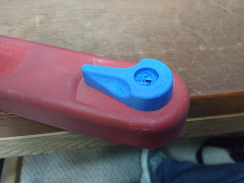
Last Sunday, Steve and I went sailing aboard the Reboot (my sailboat and home). On about the third tack, I put the winch handle in the winch but didn’t quite get it all the way into its socket. Steve was at the helm, noticed my error and shouted a warning. Alas, it reached my ears a second too late. Under the force of my cranking, the locking lever snapped. Steve immediately remarked “Well, there’s your 3D print project for this week!”
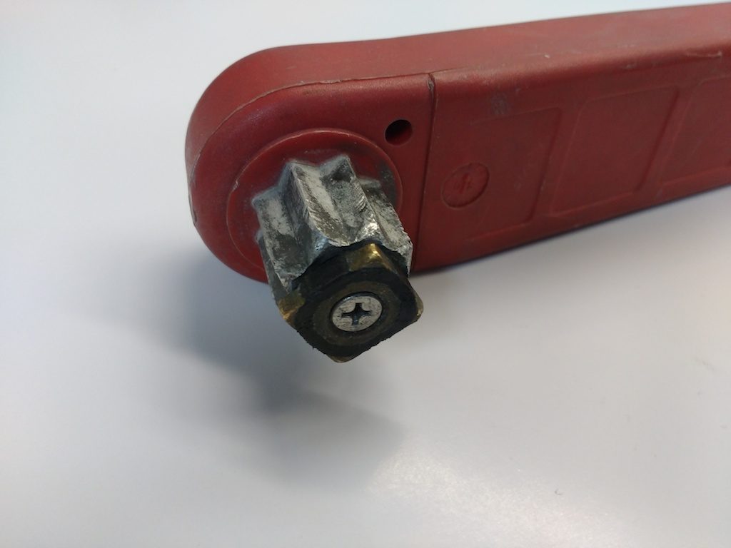
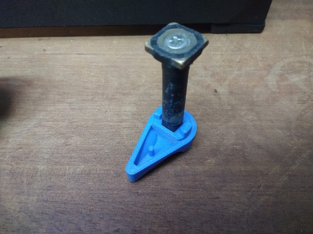
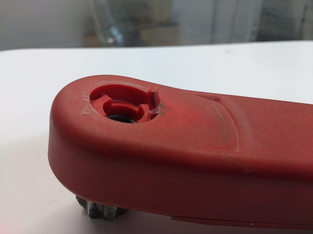
The winch handle is essentially a specialized wrench. The business end is a cylinder machined to an eight-pointed star section. This fits into a mating hole in the top of the winch. At the end of this cylinder lives a small square part which is free to twist slightly (about 22 degrees) and is spring loaded to return to its center ‘misaligned’ position.
When inserting the handle, a slight taper in the hole forces this square to twist into alignment with the star. At the bottom of its travel it reaches a groove in the socket allowing it to spring back to the center-point thus locking the winch in place. To release, you press the lever with your thumb.
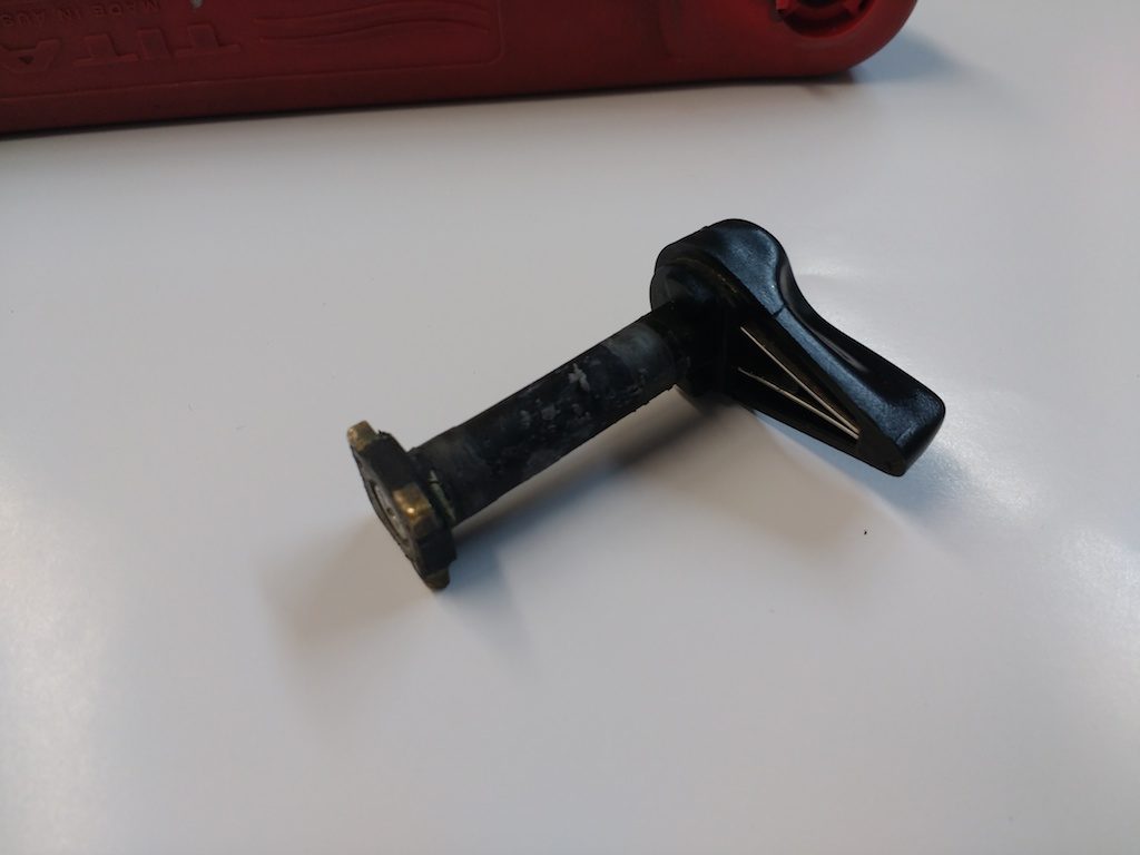
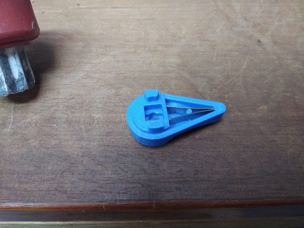
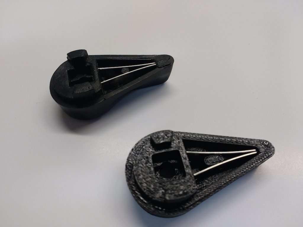
Here you can see the square part, its axle and the thumb lever assembled outside the winch. The spring is a leaf-type located in the lever.
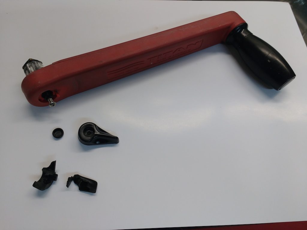
With the winch only partially inserted, apparently the full force of my cranking was borne by this square part, transferring the torque to the weakest link of the assembly: the plastic lever on top. I’m lucky it didn’t swing around and bust me in the chops when it let go!
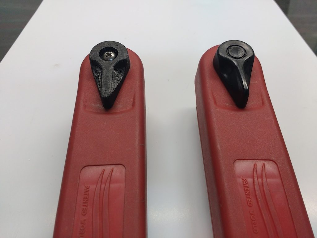
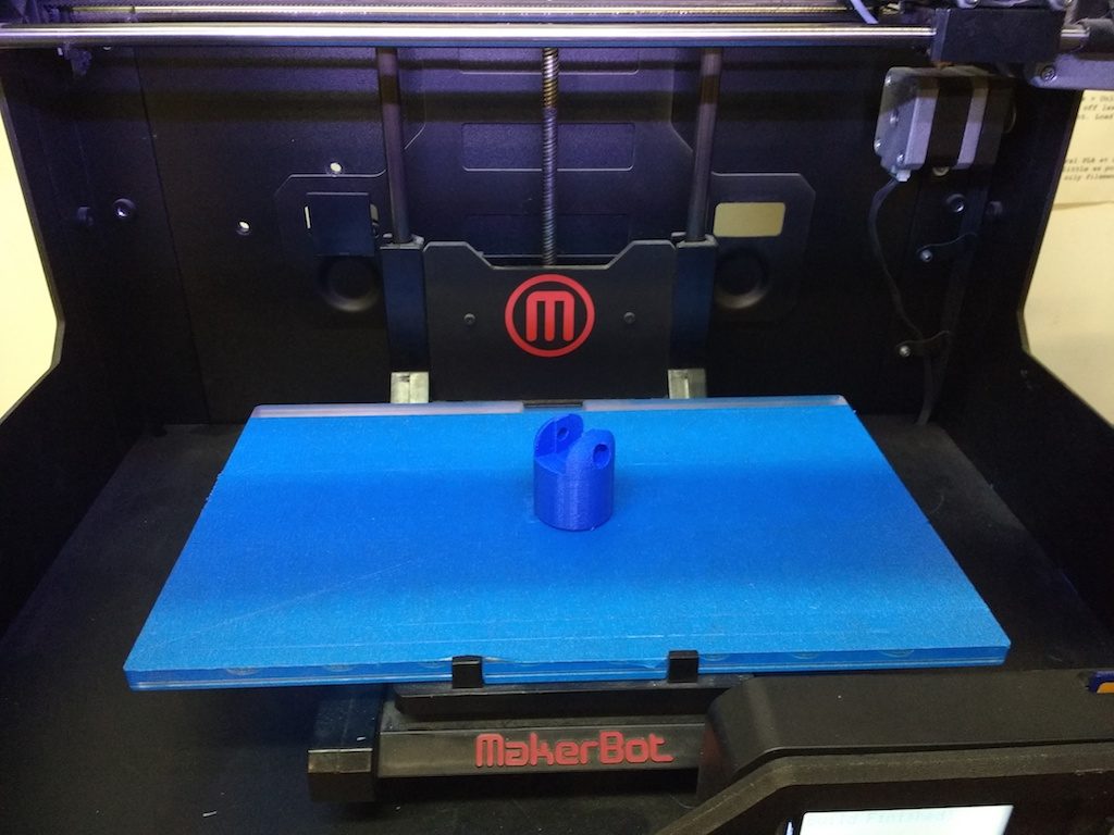
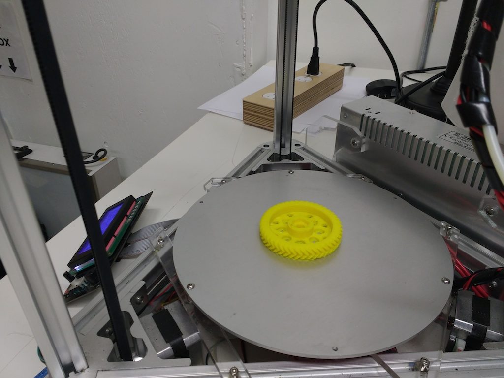
Anyway, this afternoon I modeled and printed a replacement. On a part that has to fit into an existing assembly, it’s very tough to nail the measurements just right on the first try, so I just plan on printing it at least twice. Fortunately this small part only takes 20 minutes or so to print (leaving plenty of time for this writeup). For my first pass, I simply used the blue filament already installed in the Replicator 2.
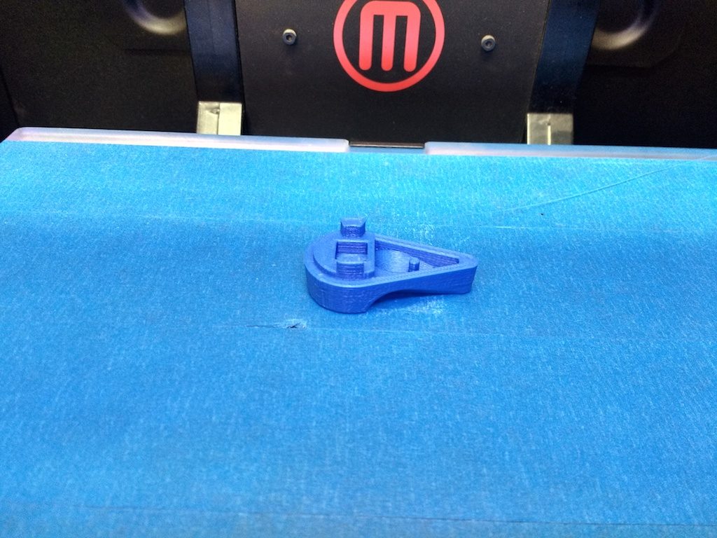
It was closer than I expected. The first, obvious problem was that I neglected to use any support material for the screw countersink. I could have tried Makerbot’s support, but from experience I know that a custom support piece works better and is easy to implement.
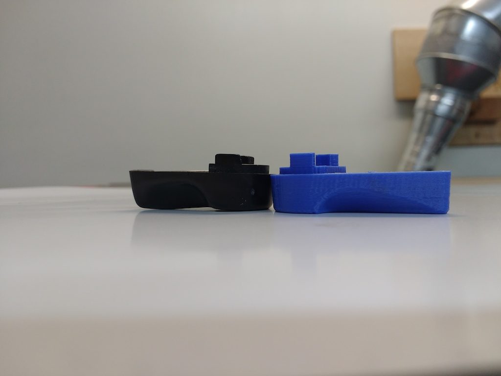
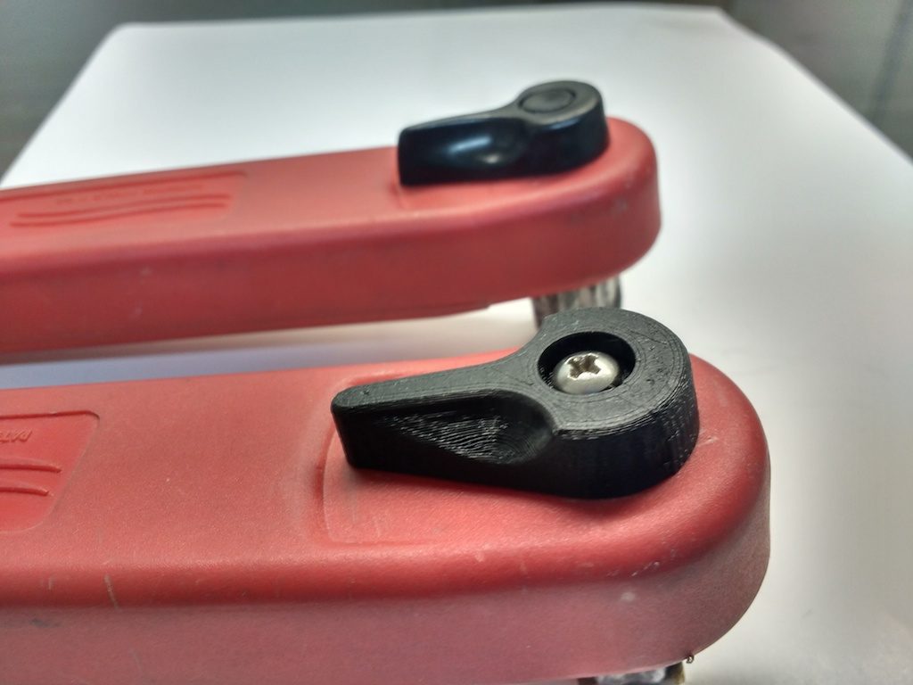
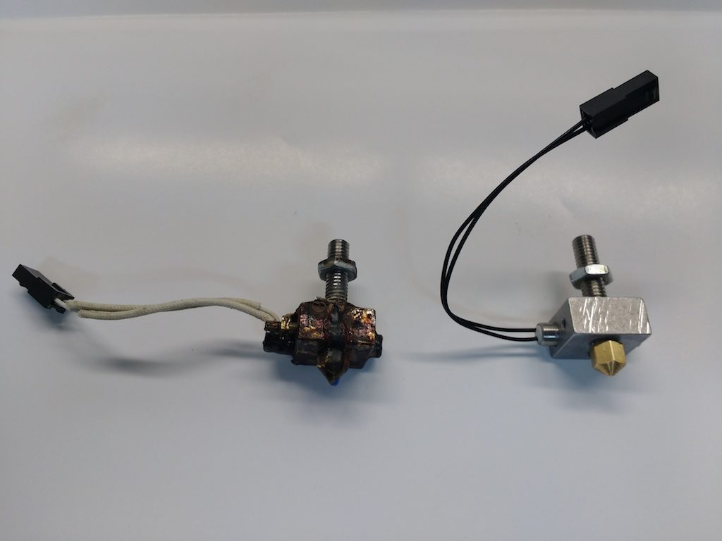
The next problem was that the part reaching into which the axle fits did not quite project far enough. In this photo you can see that I missed by nearly a millimeter (I didn’t have my calipers when I measured the original… this is as good as I could do with my pocket tape measure).
And finally, the little boss that separates the spring snapped off too easily. I made it a bit wider, and shifted it toward the axle by 1mm.
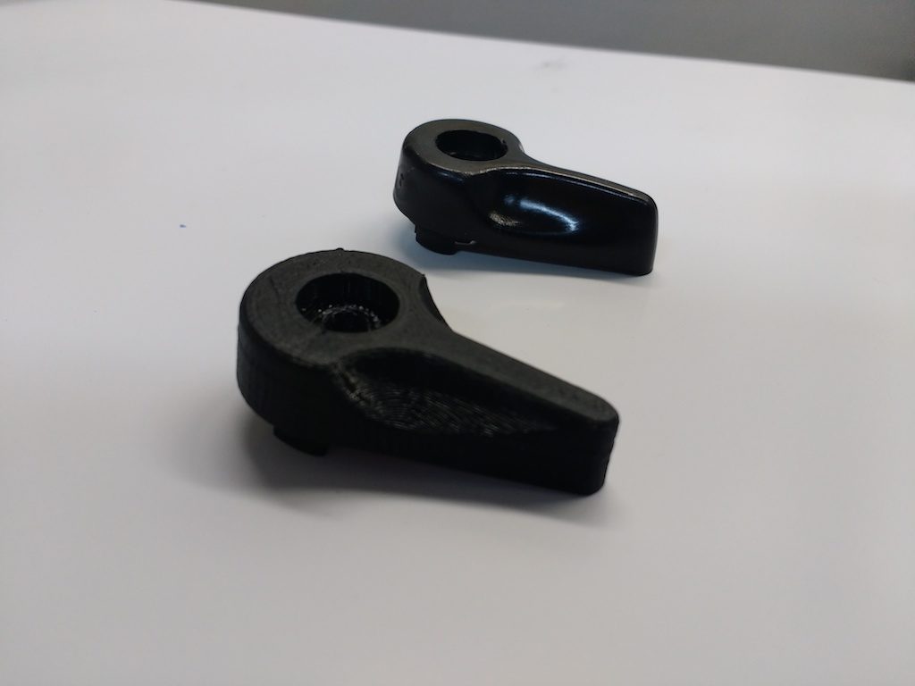
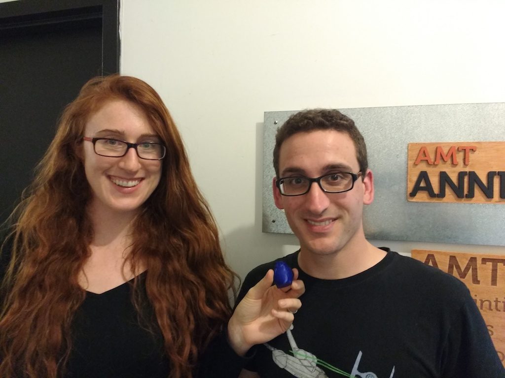
Confident in my edits, I mounted the black filament and printed version 2.
That worked pretty well, but the spring-return mechanism seemed to be binding. It turned out the spring was impinging on the inner surface of the pocket under the lever, so I hollowed it out a bit more and printed again.
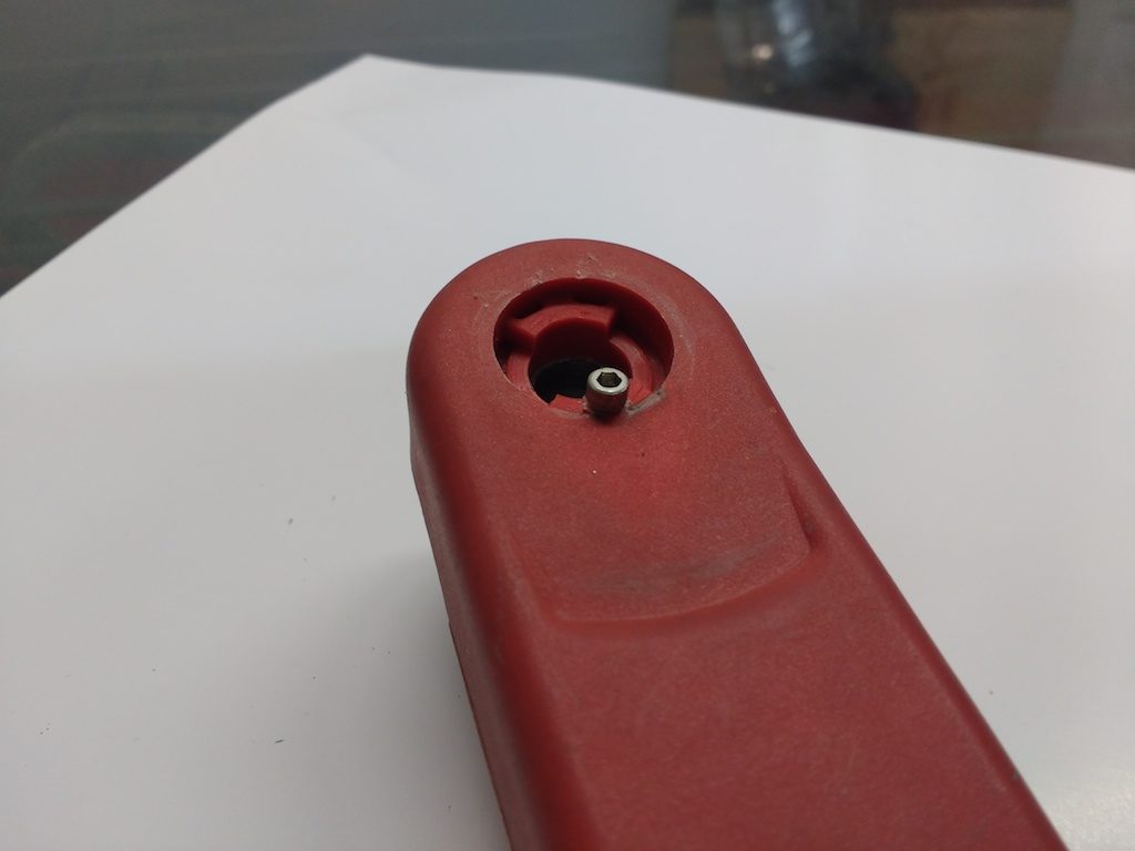
Success! …except now I found another problem: the boss on the winch handle itself was nearly broken off. This probably happened at the same time. Unfortunately, printing the entire handle is probably not feasible: I suspect there’s a steel part inside, and the plastic seems to be tougher material in general.
Instead, I drilled a hole and inserted a small screw. Seems to work so far; I hope it lasts!
Modeling
Modeling a complex shape like this can be a bit bewildering, since there are so many approaches one might take. Where do we start?
I find it useful to first consider the orientation that the part is printed in. Since there are lots of holes and important protrusions on the bottom, I decided to print it upside-down to minimize the use of support material.
This decision immediately necessitated a slight variation from the original design. This photo doesn’t show it very well, but the original thumb-handle projects upward ever so slightly. On mine it’s flat.
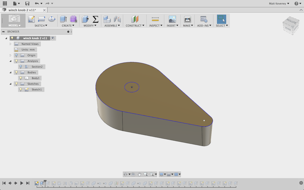
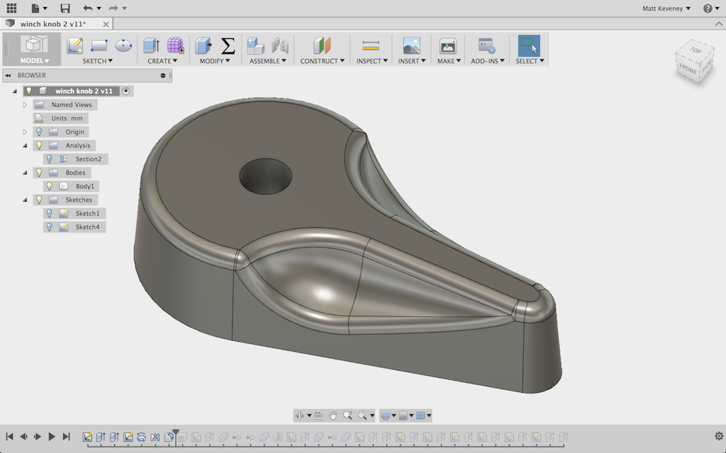
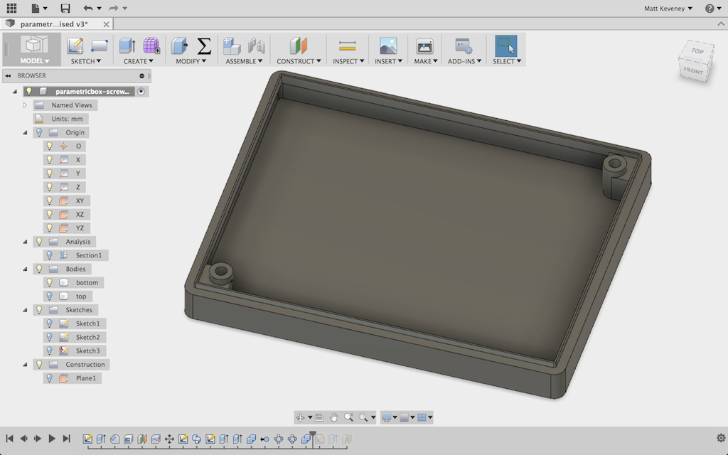
Then, what plane to start sketching? I chose the plane at the base of the lever, but above the parts that protrude into the winch handle body. This section is easily measured and clearly defines the basic body of the lever, so it made sense to start there.
That profile is extruded with a slight angle (I picked 4 degrees), which follows the design of the original part. The original was undoubtedly injection-molded, which requires an angle like this to allow the part to be easily extracted from the mold. We don’t have that restriction with 3D printing but I mimicked it anyway (here shown upside-down).
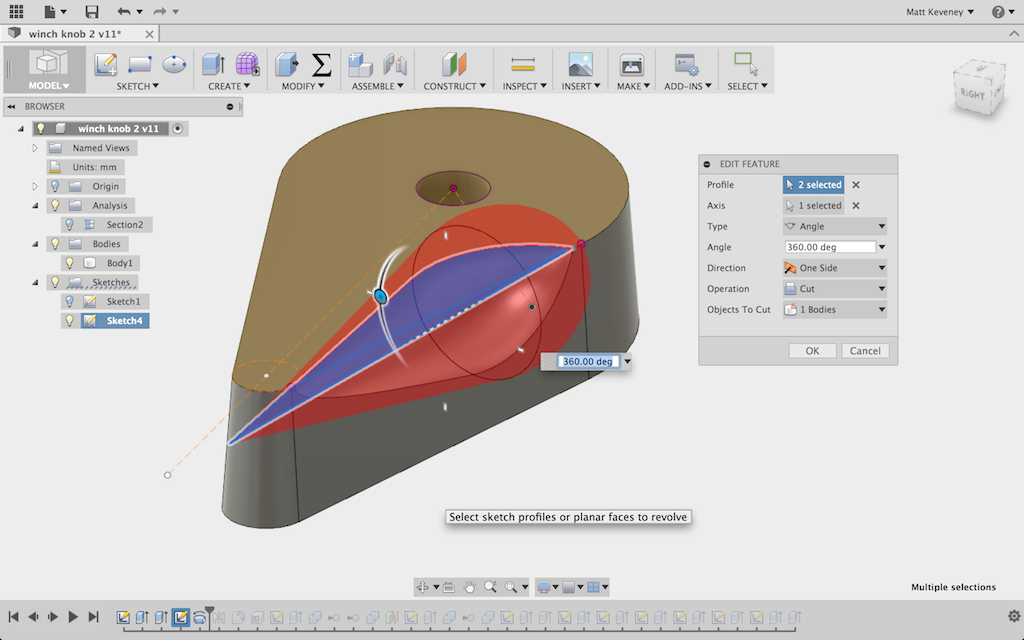
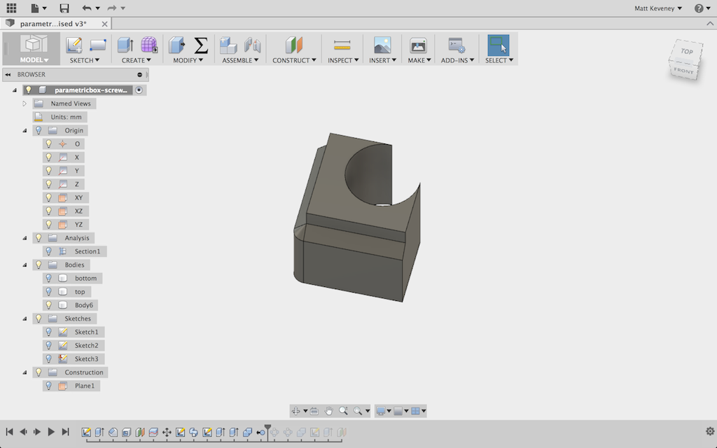
Then the thumb cutaways. These are made by revolving a profile that was made by eye and a bit of trial and error. Mine does not exactly match the original but looks nice and is functionally equivalent.
With a fillet added, it looks even better and is quite comfortable to handle.
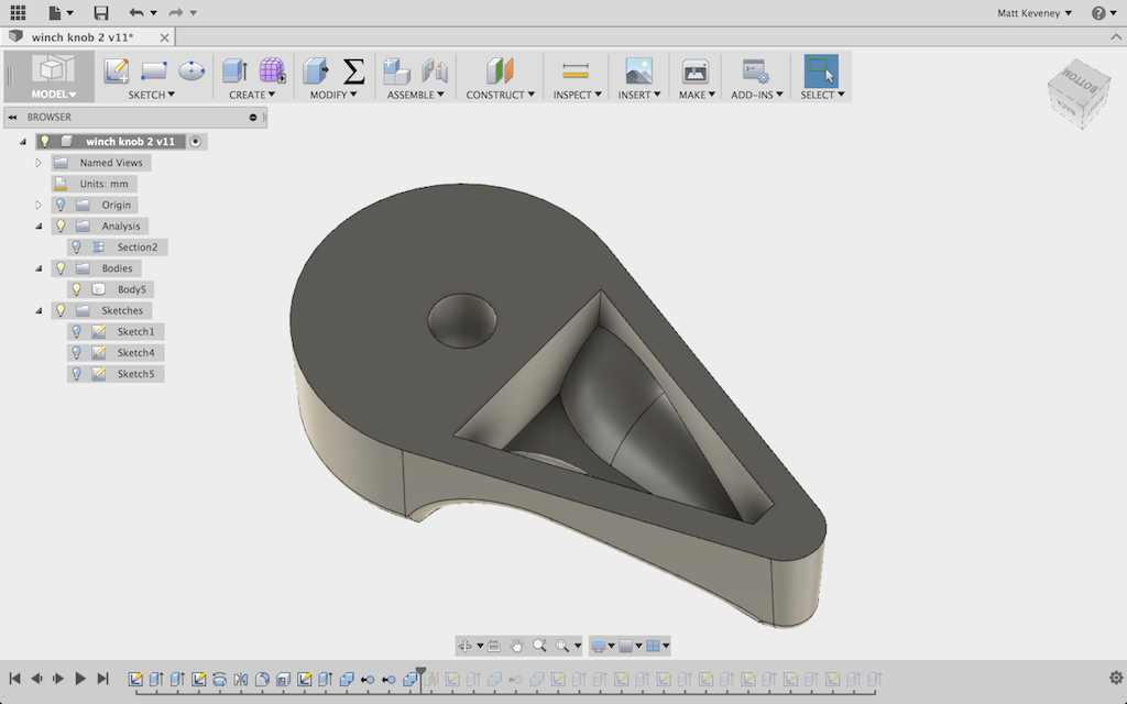
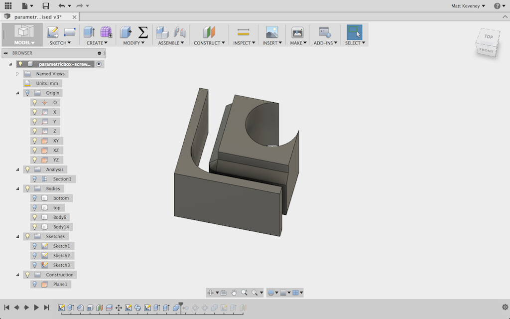
A pocket must be defined beneath the lever to accommodate the return spring. This took a few tries to get right. My initial thought was to simply extrude a pocket, straight in from the bottom, but that cut through the thumb cutaways.
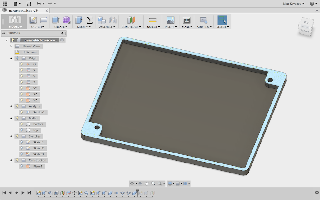
Instead I used the ‘shell’ command to uniformly hollow-out the bottom. Then to thicken up the portion around the pivot, I extruded a section. This went through the lever, so I used a sequence of combine operations to eliminate the protrusions, much as I did with the parametric box update.
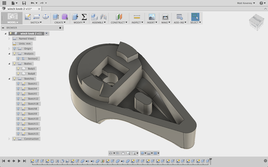
The remainder of the model consist of straightforward sketches and push/pull operations. I’ll upload the model for you to explore on your own if you’re interested.
It seems to be working so far. Time will tell how long it lasts. PLA degrades in sunshine, so I might have to revise and reprint at some point, perhaps with PET or another more durable material. In any case, I hope this has shed a bit more light on how you can tackle your own 3D print design challenges. If you get stuck, I’m here to help!
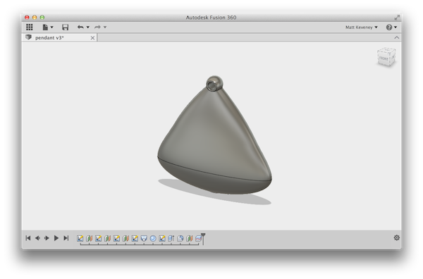
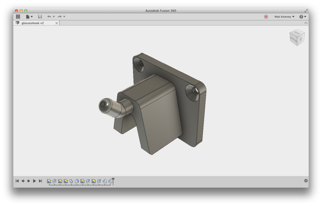 It’s always satisfying to go from idea to finished thing in one session. This one worked, but everyone had thoughts for improvement as soon as it came off the build plate. The glasses fall off unless they’re very carefully placed on the hook. Maybe a flat section on the bottom and a wider hook portion would make it a bit more reliable. Here’s the Fusion 360 model, in case you’d like to have a closer look, and maybe tackle those improvements!
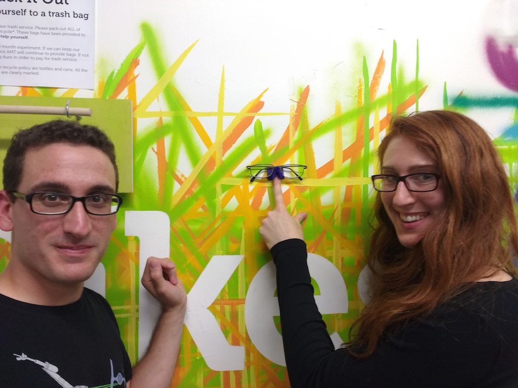
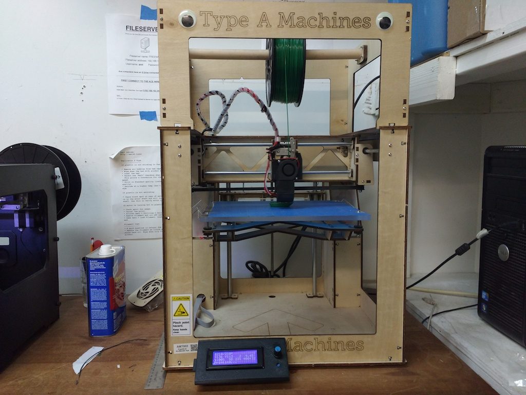 Previously one had to print tethered to the PC, which can be prone to communication errors, and requires a bit of know-how to do basic things like leveling the build plate. Fortunately the Type-A controller is a standard
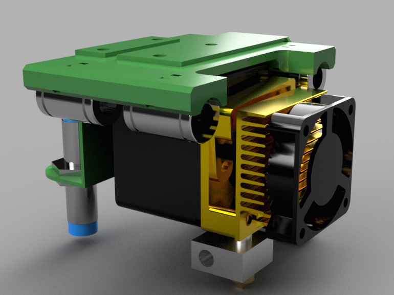
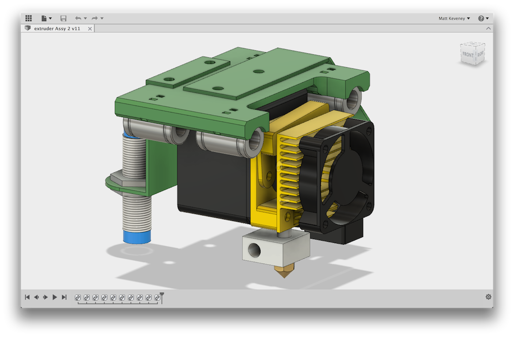
 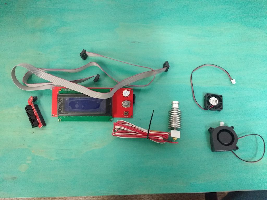 I designed the LCD case/bracket and fan shrouds in Fusion360. Let me know if you’re interested in how that was done.
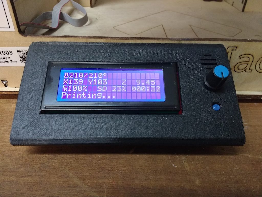
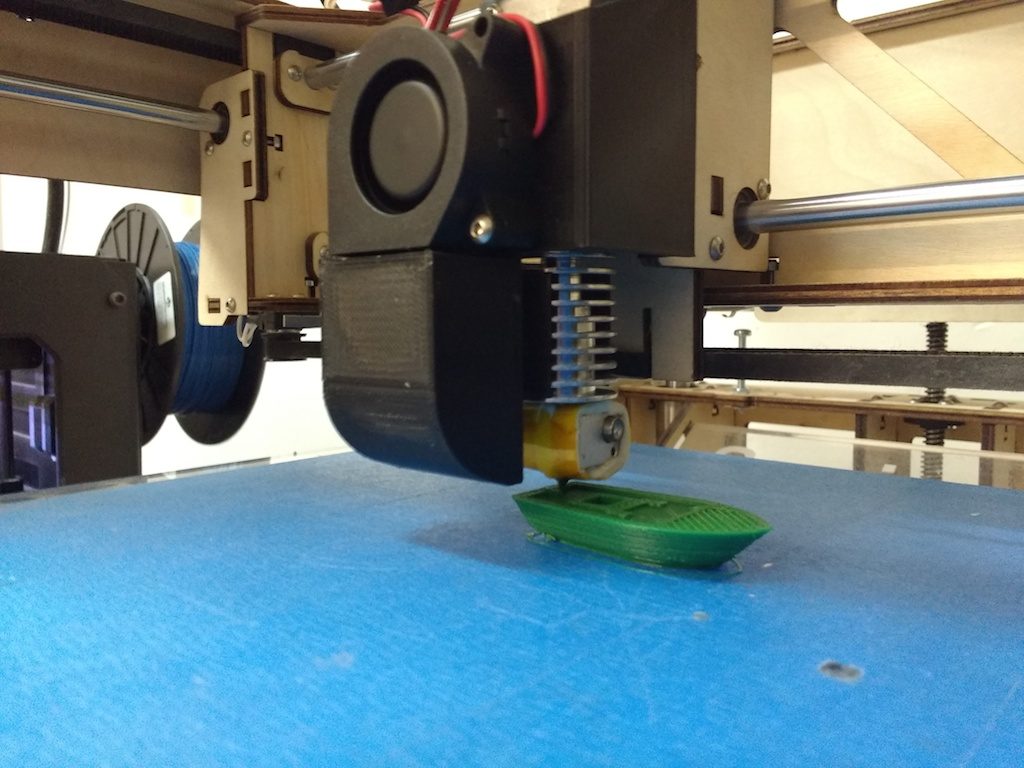 It all works fine, but I’m chagrined to admit that the quality is still a bit disappointing; layers are a bit misaligned, and extrusion is inconsistent. I think maybe belts need tightening, and maybe the extruder pinch-roller needs a stiffer spring. Still, for less than $20.00 invested, we’re not out much if I can’t manage it.
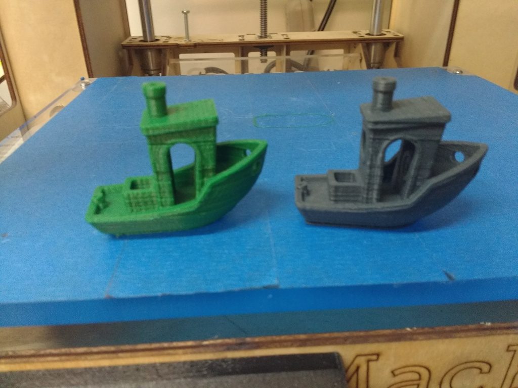 It also needs updated documentation, which I’m tackling next. If you’re experienced and anxious to try it out, essentially the workflow is this:
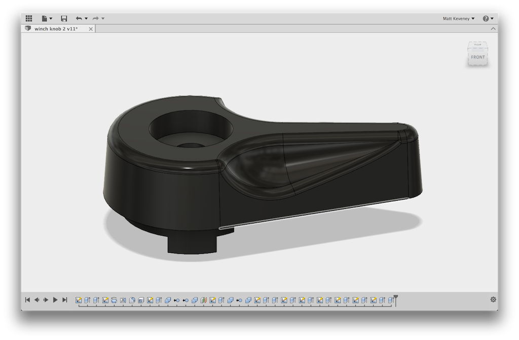

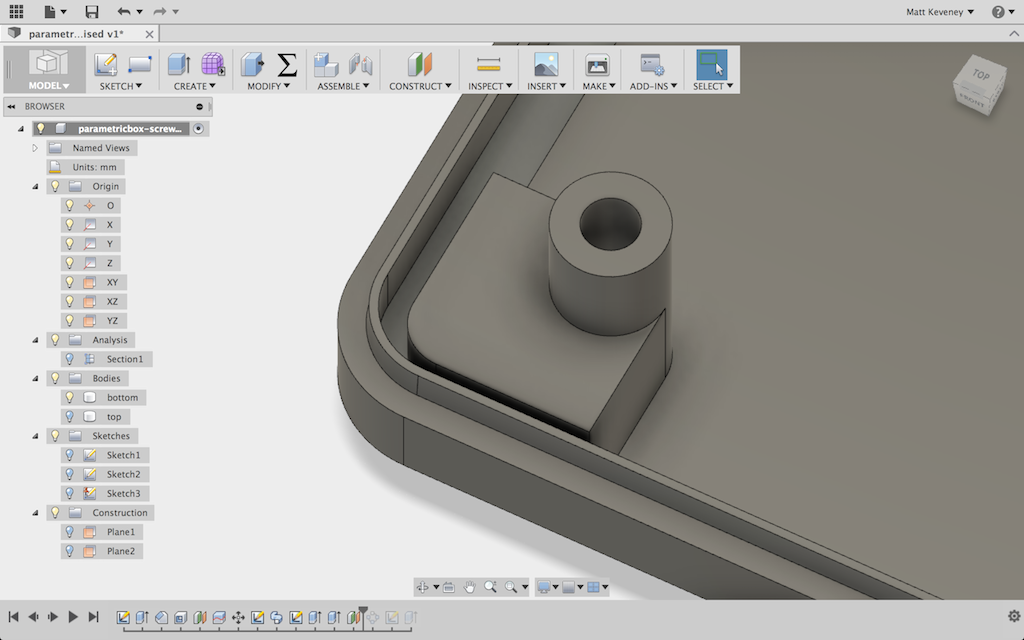
 That all may seem a bit convoluted, but it now seems to work with any reasonable set of parameters. A much simpler solution would have been to eliminate the chamfer altogether, or make it a small fixed dimension that would have avoided the problem in the first place.