Category: 3D Printing

Well 3D printing of course

A parametric design for 3D printed boxes

…and my thoughts on filament quality.

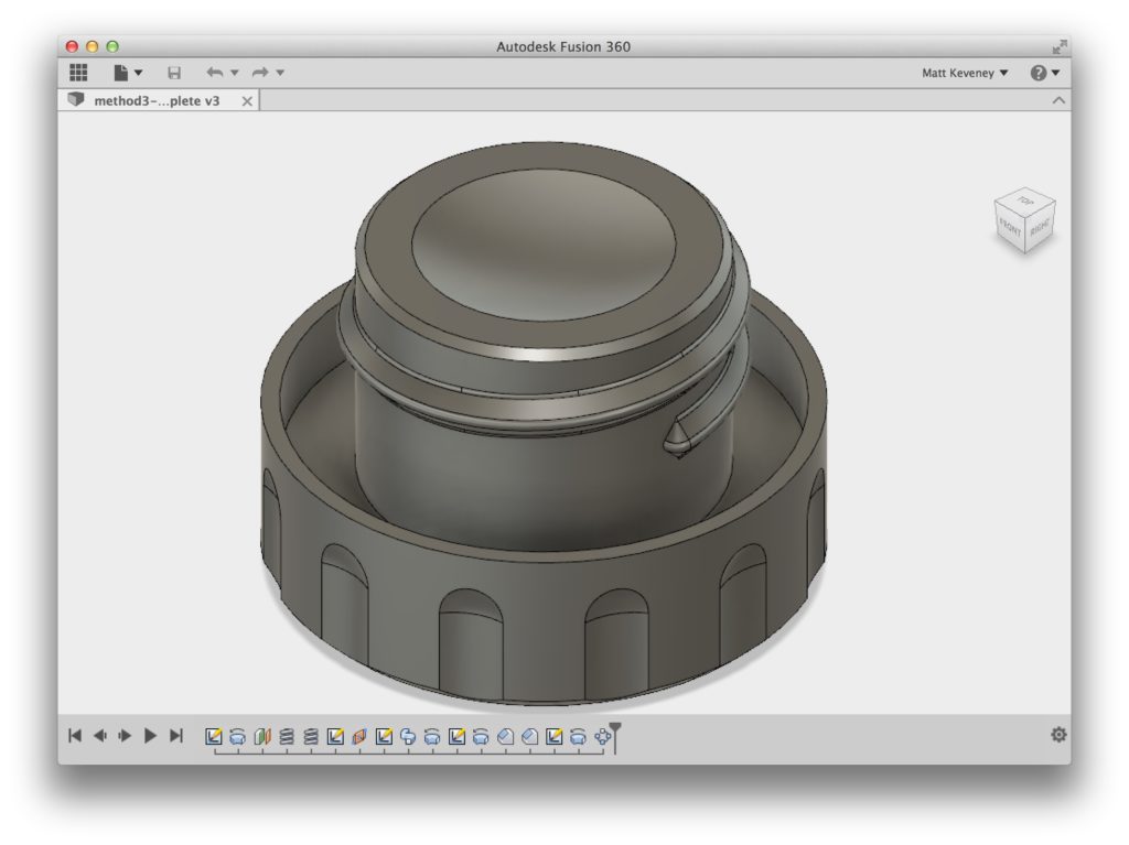
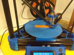
3D printing presents some special challenges when designing parts that must fit together. In this article I’ll explore this briefly while creating a simple plastic box with a close-fitting lid. I’ll try to make the design as flexible as possible, using Fusion 360’s parametric features.

A simple rectangular box is what I’m after. The top of the box will fit over an interior lip designed into the bottom. The side faces of the top and bottom will be flush with one another when the top is on. The vertical corners of the box will be rounded. The edges along the upper and lower face will be chamfered.

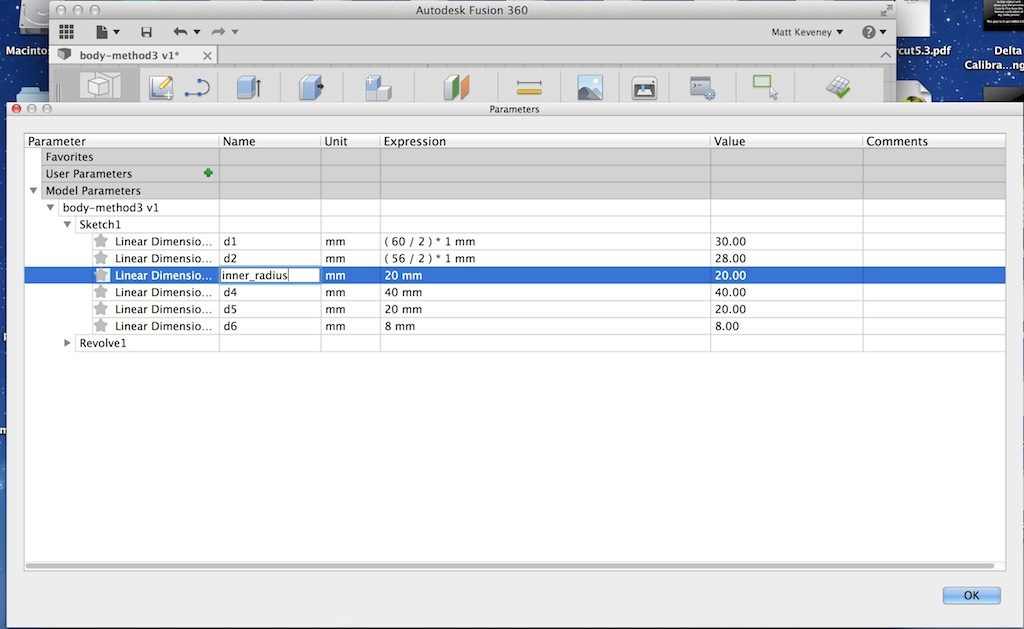
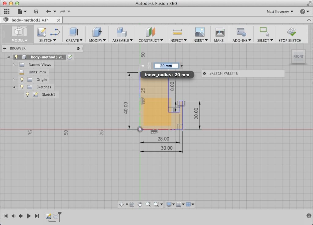
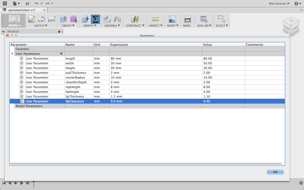
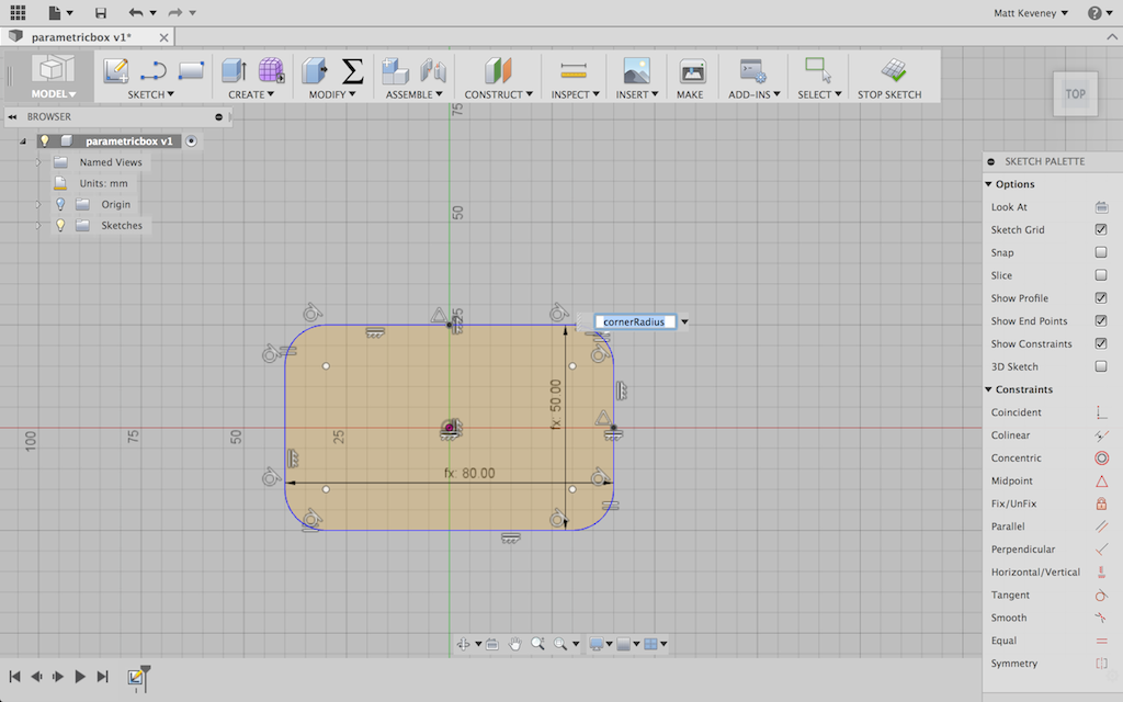
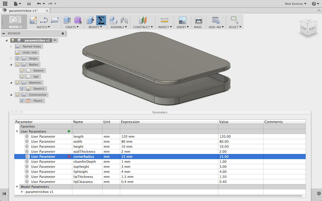
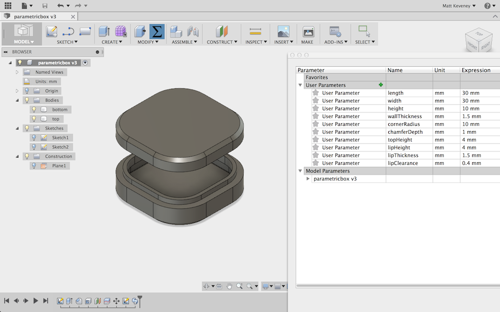
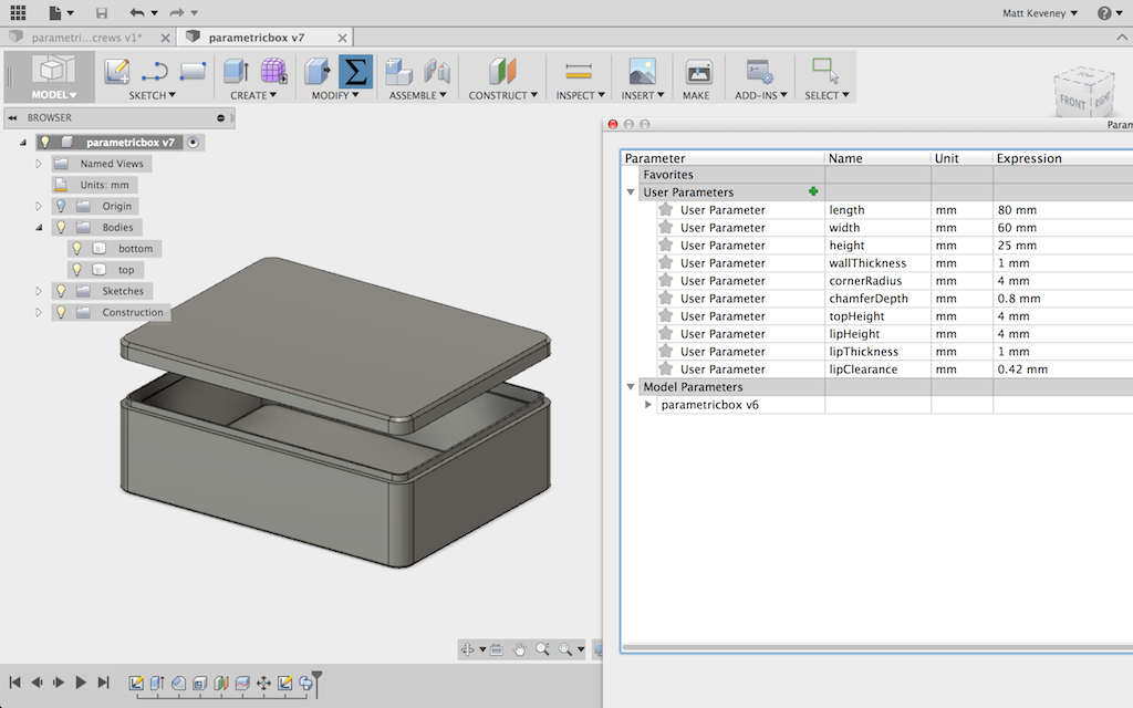
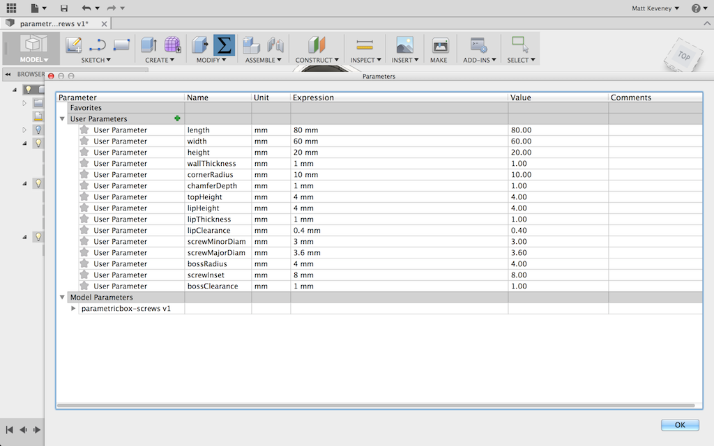
For starters, I’ll add user parameters for the features I know I want to be adjustable. I can always add more as needs arise. I’ll initialize my parameters to something that seems reasonable.

pb_parameters

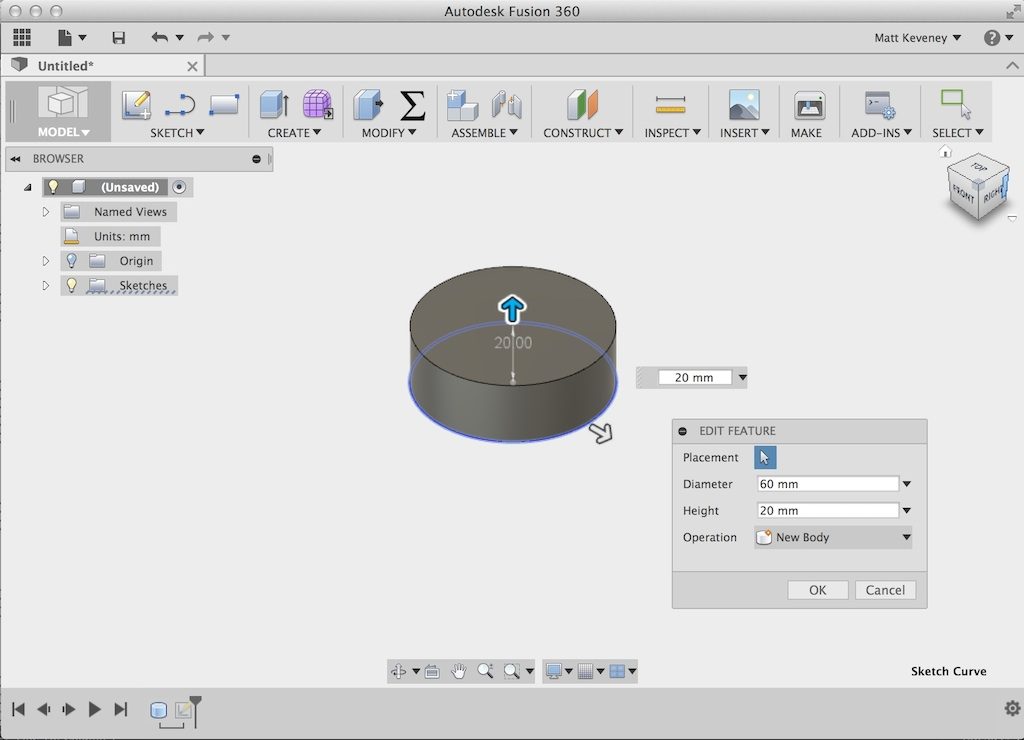
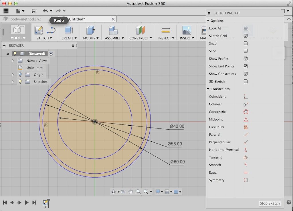
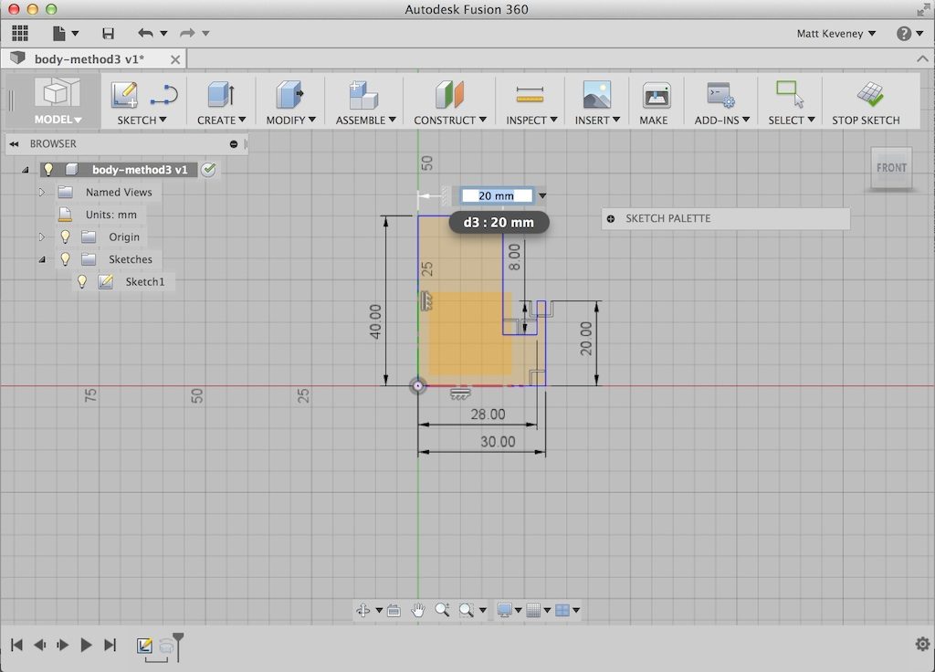
I’ll model a solid box and use the shell tool to hollow it out. Then I’ll use the split tool to cut off the top. I start with a sketch of the perimeter of the box, viewed from the top. Note that my dimensions reference the parameters I just entered. Note also that I draw the box centered around the origin. This will come in handy later.

pb_bottomsketch

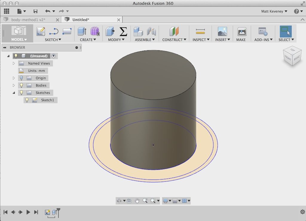
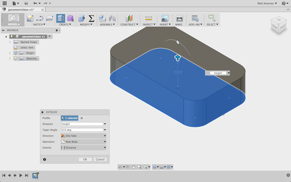
I extrude this to create the box. For the extrude height, I reference my height parameter.

pb_boxextrude

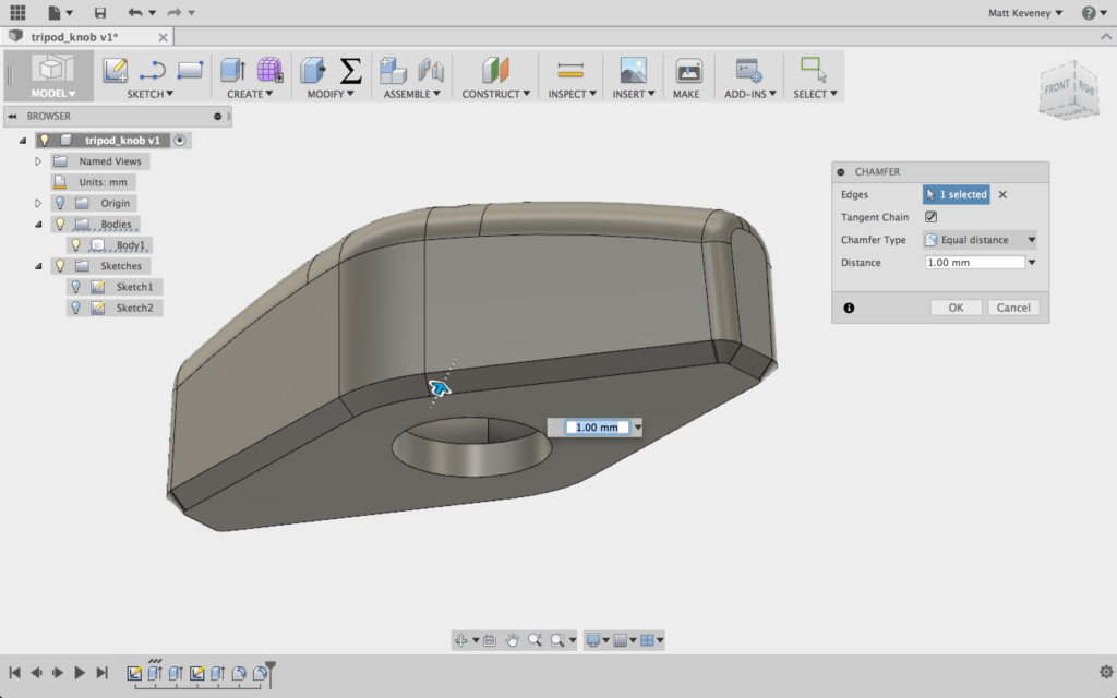
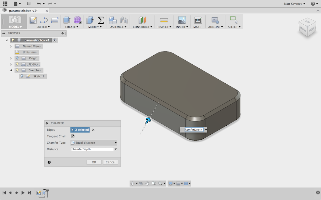
Next I chamfer the top and bottom edges. I can select all the edges and apply a single chamfer operation. It’s important to apply this before hollowing out the box, since the chamfers might excessively thin the material at the corner or even cut through.

pb_chamfered

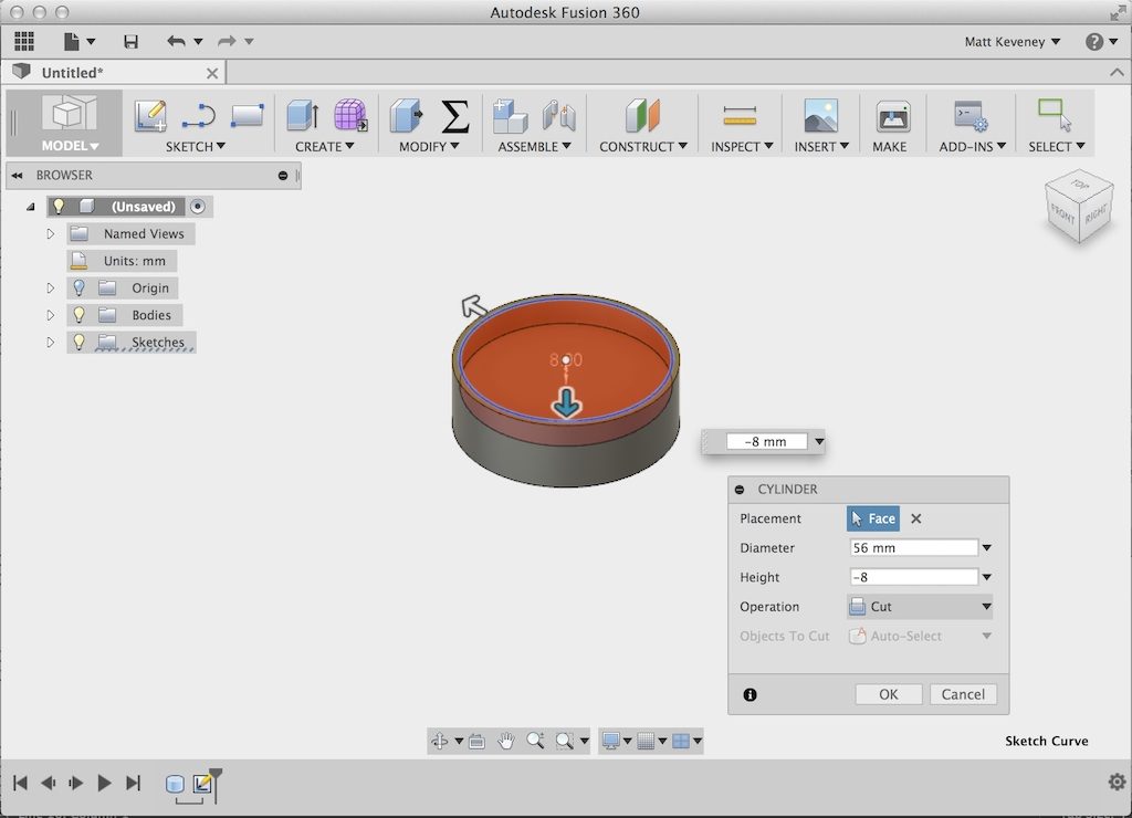
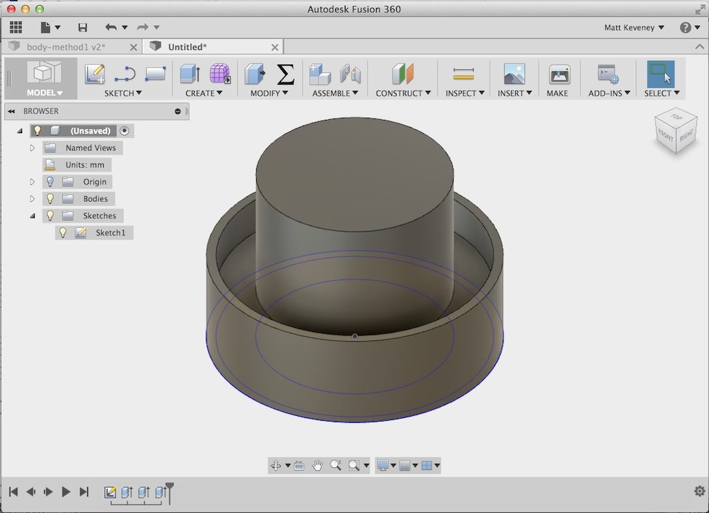
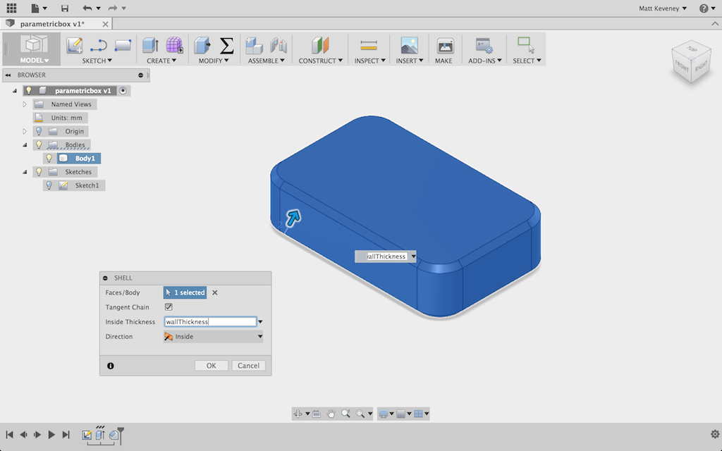
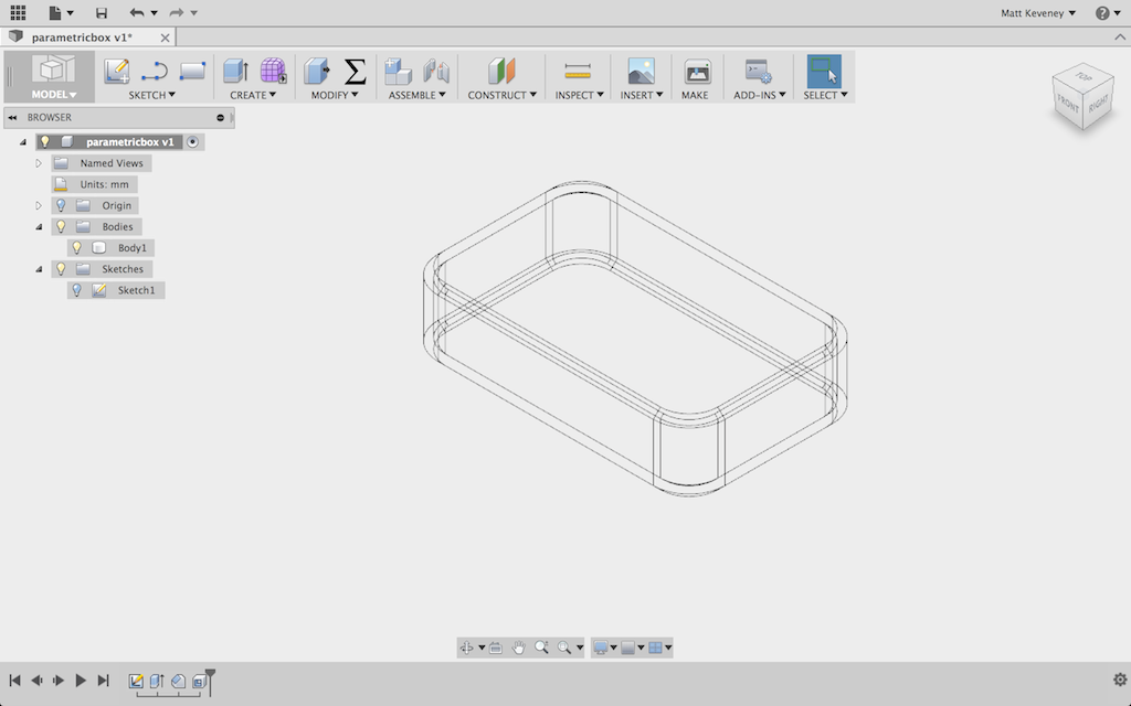
Now I’ll hollow out the box using the _shell_ tool. Since I want an internal cavity, I select the entire body.

pb_shelled

I’ll briefly switch to wireframe view to confirm that the inside has been hollowed out.

pb_shelled_wireframe

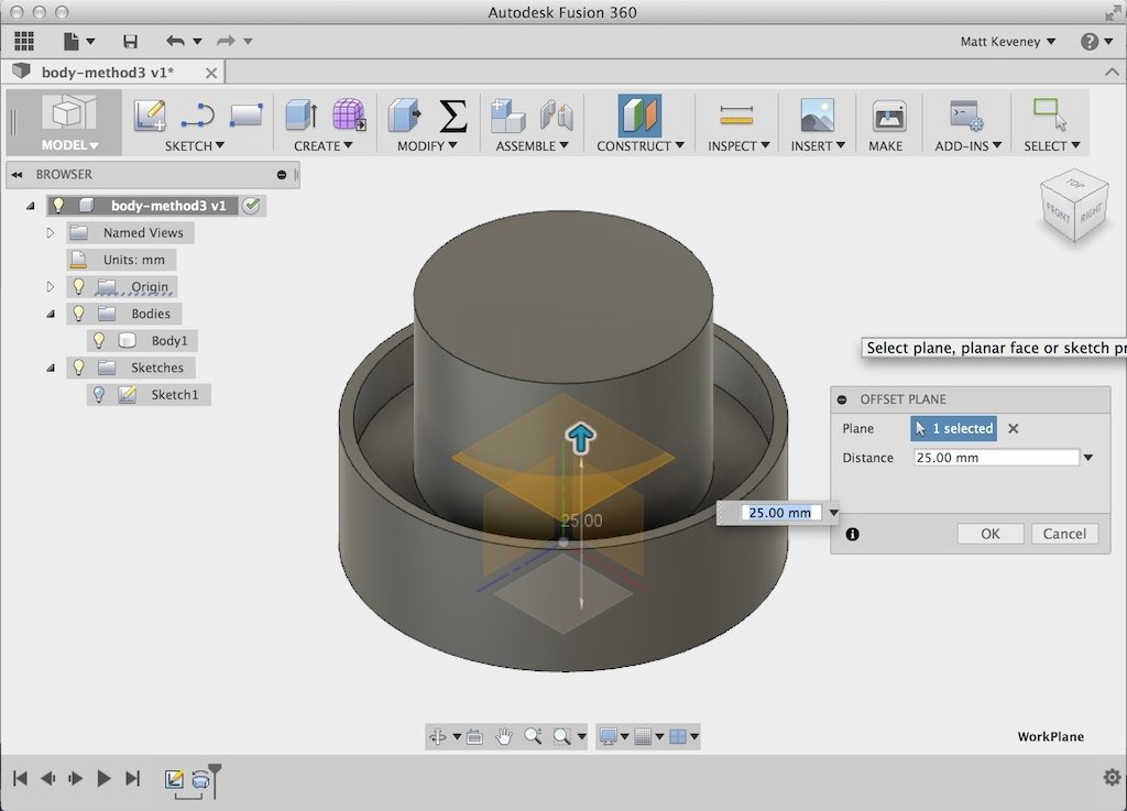
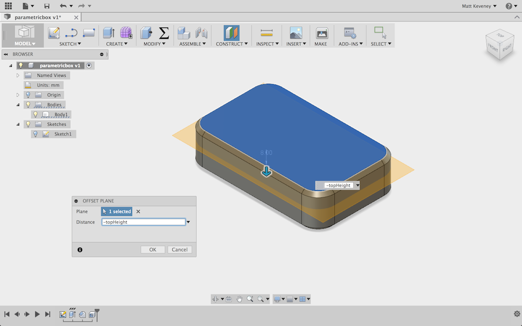
Now, I make a construction plane offset downward from the top of the box by the height of the box top.

pb_workplane

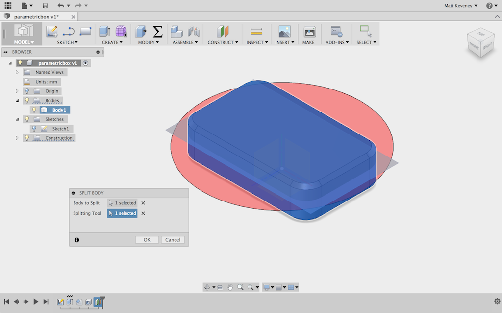
I use the Split body tool to separate the top from the bottom.

pb_split

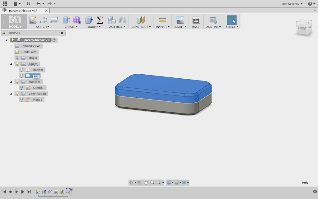
It’s a good idea to give the bodies functional names at least. If I were doing more extensive work with this box, it would make sense to put the top and bottom into separate components too, but I’ll skip that for today.

pb_bodiesnamed

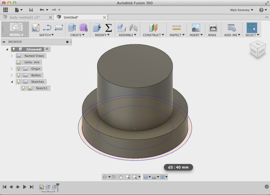
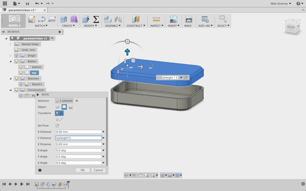
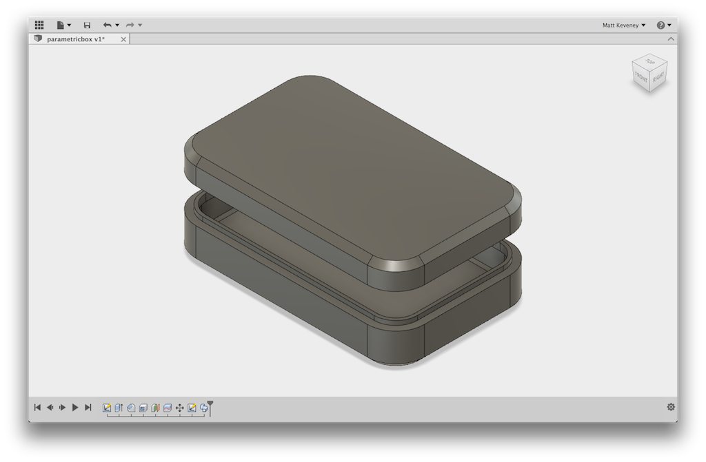
Now, just so I can see what I’m doing, I’ll move the box top up a bit. I’ll re-use the lip height for this dimension.

pb_topmoved

This is a good place to stop and check that the parameters actually work. I’ll make a few changes and visually check that the model seems to respect them. Here’s a wide, flat version:

pb_wideflat

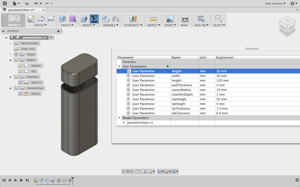
And a tall, narrow version:

pb_tallnarrow

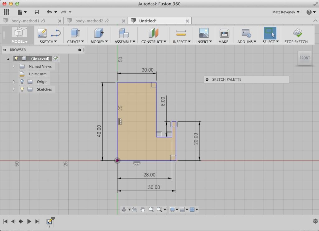
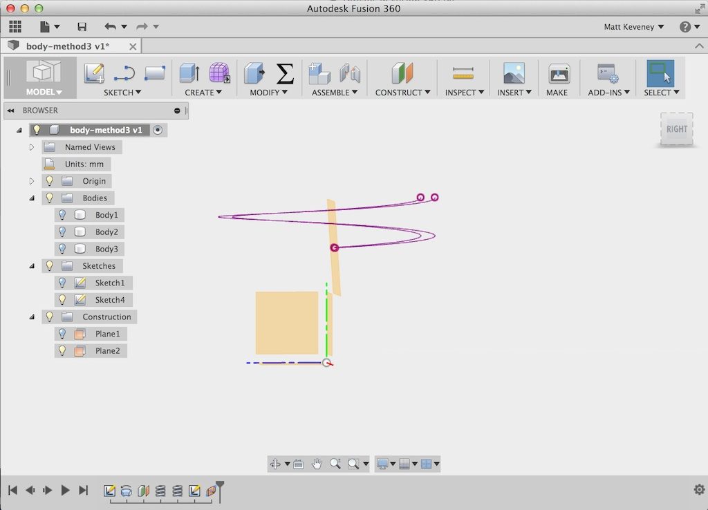
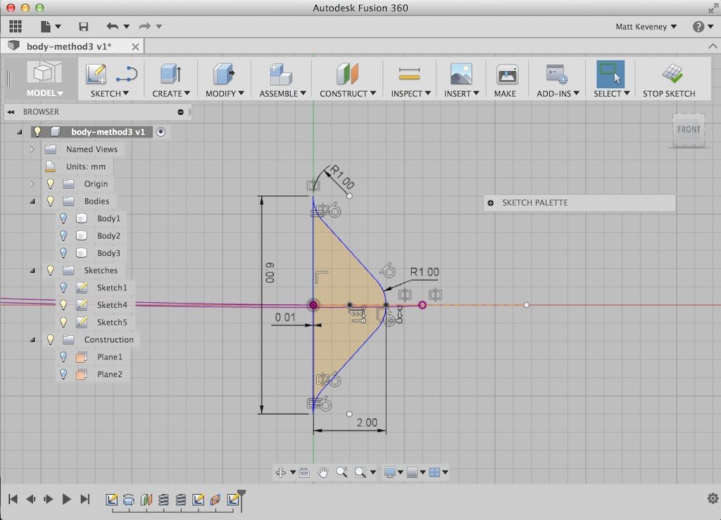
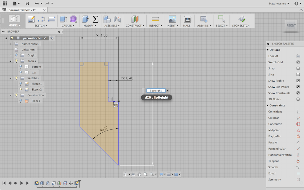
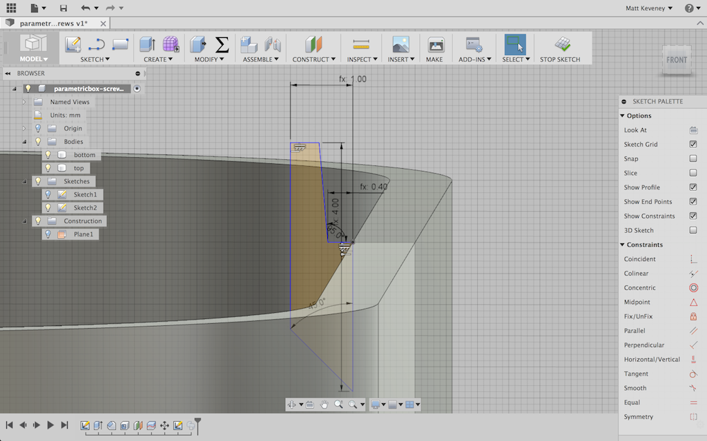
Now to tackle the lip. I want the lip to project inside the box bottom and to leave a bit of clearance so that the box fits nicely. I don’t want the lip to extend all the way to the bottom of the box, so I’ll create a sloped face on its bottom edge to eliminate the sharp overhang. I hide the top first. Now, since I had the forethought to center my box, I can create my sketch on the default XY plane.

I then project the intersection of the top right inside corner and anchor the rest of the profile to it. Note particularly the small horizontal segment dimensioned to the ‘clearance’ value. I’ll adjust this parameter experimentally to get a good fit.

pb_lipsketch

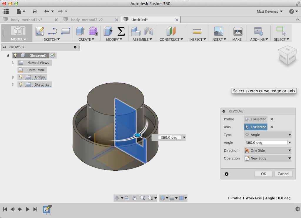
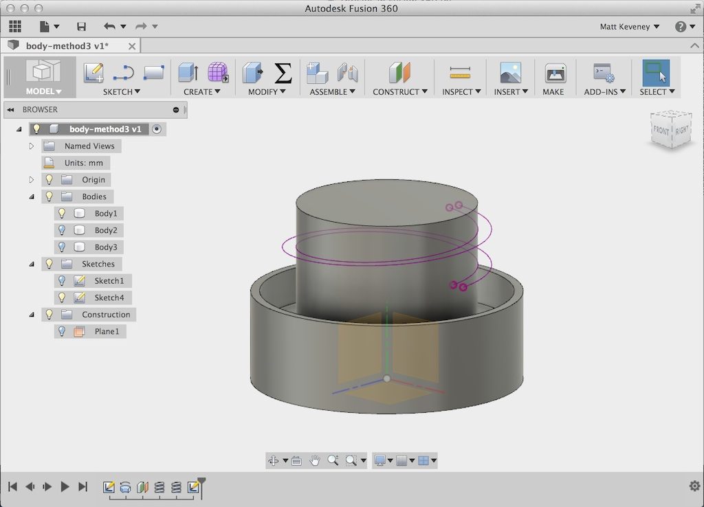
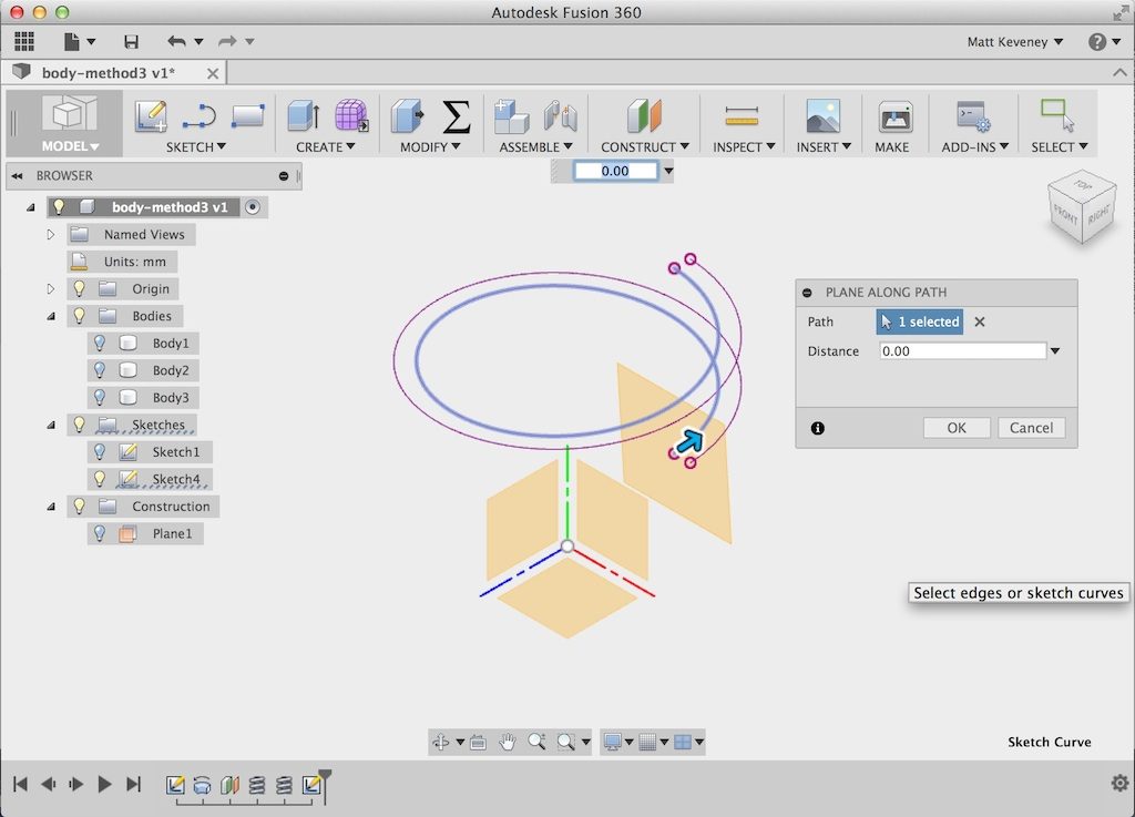
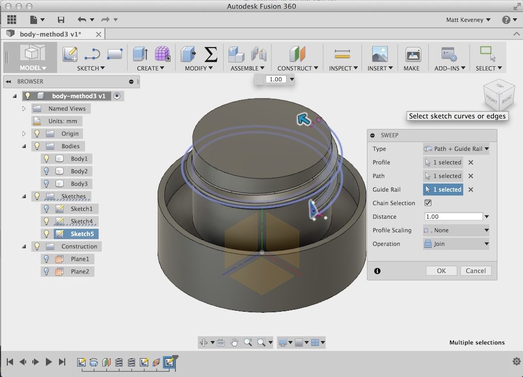
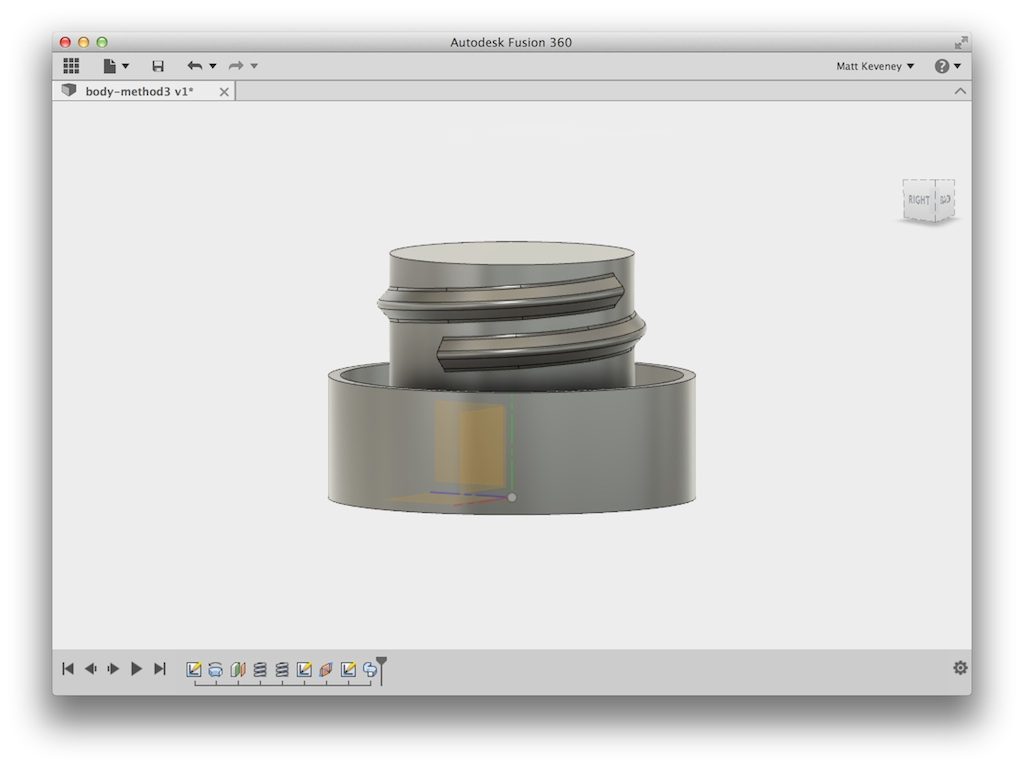
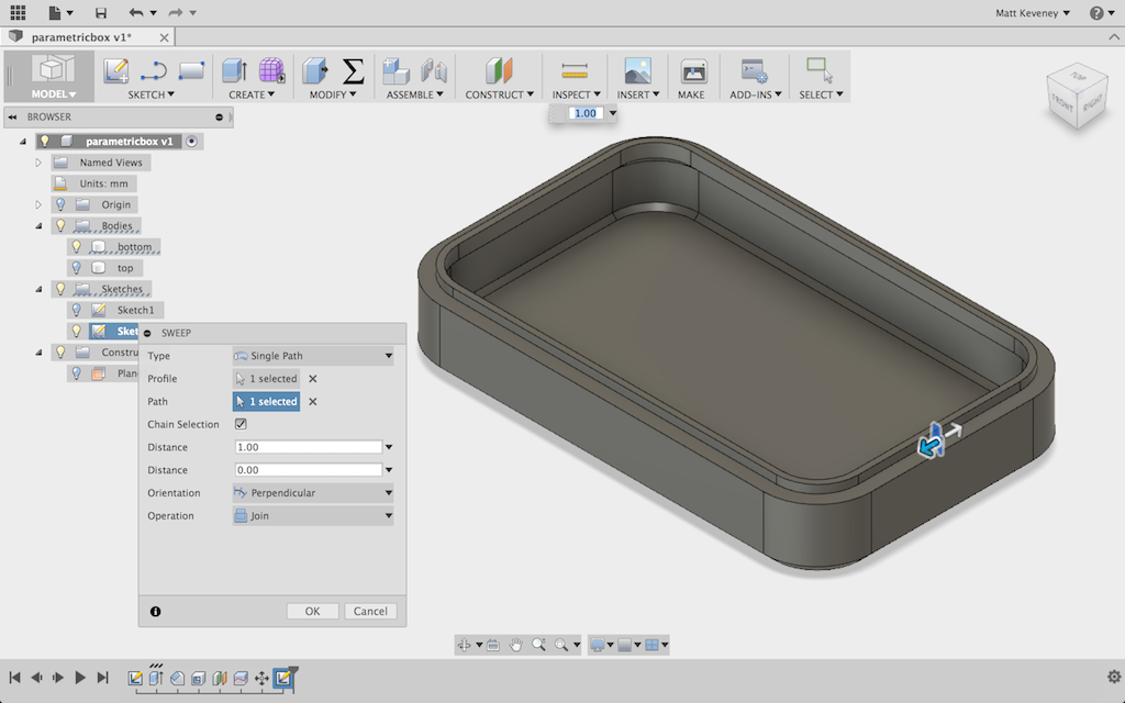
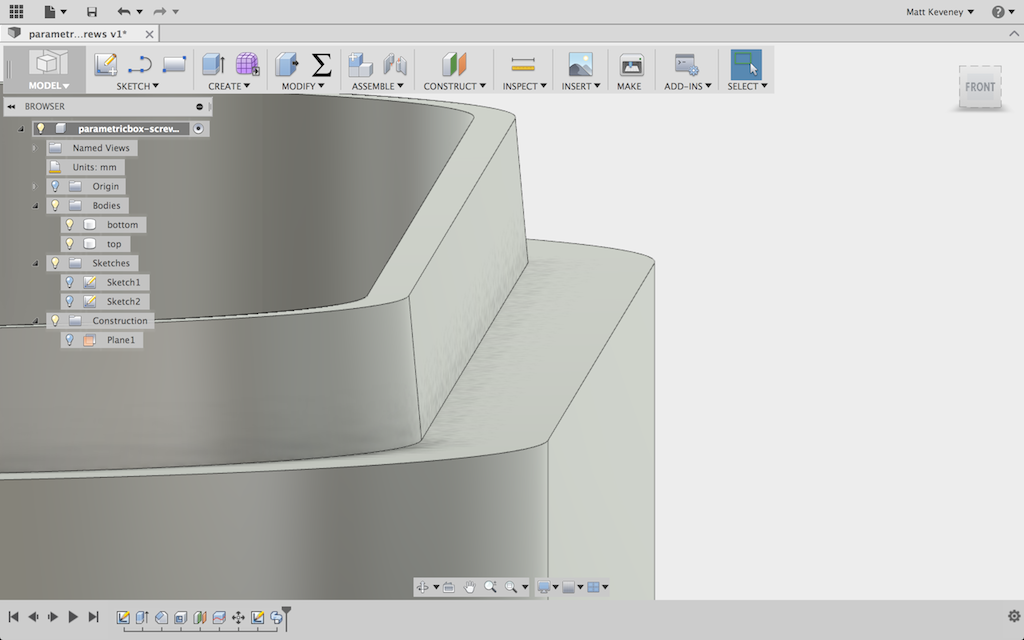
With the profile done, I use the sweep tool, specifying the top inside edge of the box as the path.

pb_lipswept

My box model is complete; now the tweaking begins. I just guessed at the initial clearance value of 0.4mm, since that size has worked reasonably well in the past. But I also know from experience that I can’t predict this perfectly. Even though the mechanism of my printer is very accurate, the final part dimensions can still vary due to slight inconsistencies in filament width, differing filament temperatures, slicer settings, etc.

pb_complete

Now for a bit of a diversion: Whenever I discuss dimensional tolerances, someone inevitably asks whether “high quality” (read: expensive) filament will solve the problem. Certainly the premium filament vendors would like you to think so, but it isn’t true in my experience. No matter how much I spend, I see variations in filament diameter and melting temperature that are significant enough to cause slight variations in part dimensions.

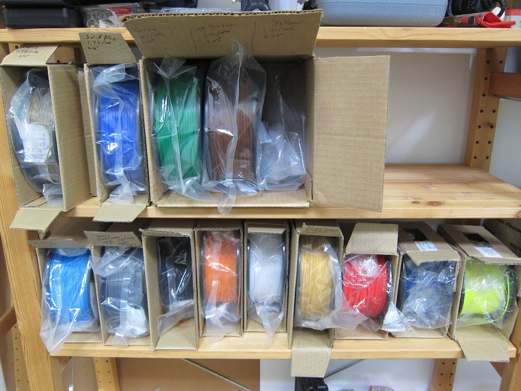
I now use inexpensive filament mostly from vendors on eBay. I choose vendors with a reasonable level of positive feedback, and have had very good luck lately (14 spools purchased over the last 8 months or so; all work well; most under $19.00/kilo including shipping). When I did choose a more expensive vendor (still just $22.00/kilo), it was only because the cheaper places didn’t have the colors I wanted!

pb_filaments

I think that filament quality in general has improved in recent years.  Here’s a fairly current review of some cheap filament from Hobbyking that seems to agree (Hobbyking is currently selling $10.00 spools that have just 1/2 kilo, so be sure to compare fairly). I think the situation was worse a few years back, so check the dates on what you read.

I also think that some of the complaints may be from folks venting their frustration instead of acknowledging the simple fact that all manufacturing technologies are imperfect.

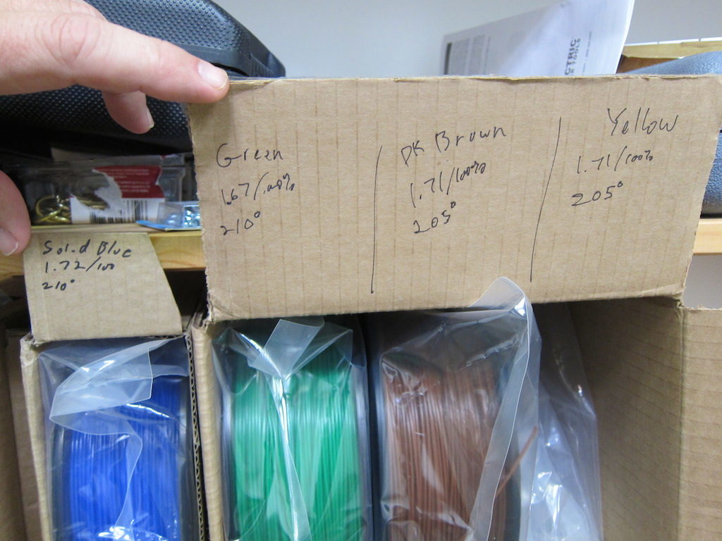
Instead, we can learn to work within the limits of the technology, including variations in filament properties. To help with consistency, I always measure my filament diameter and record it along with the temperature and any other non-default slicer settings.

pb_filamentsettings

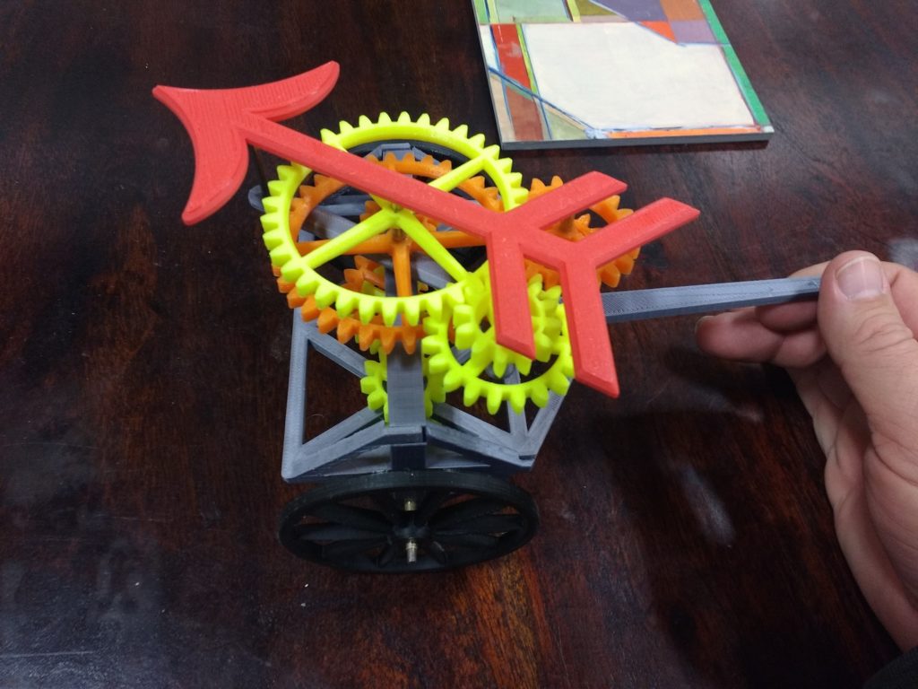
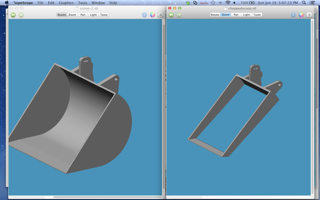
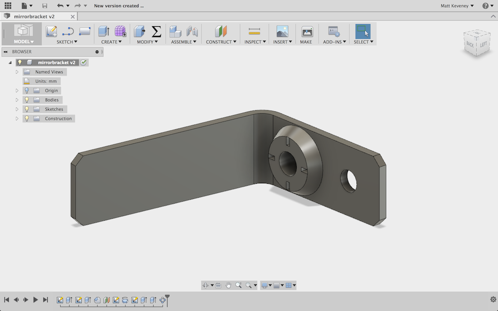
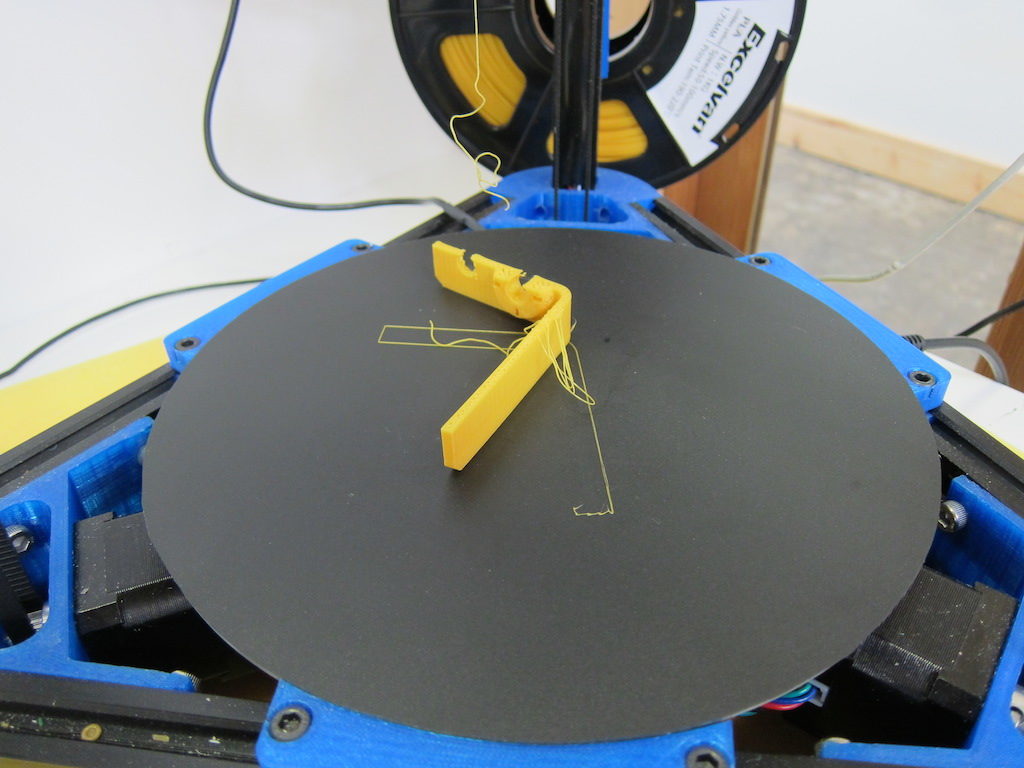
Even with all that preparation, a really close fit always seems to require some experimentation. Rather than fight it, I design my parts to accommodate these experiments with a minimum waste of time and material. Sometimes I make an abbreviated copy of the part so I can test the fit without printing the entire thing out. The following screenshot is the model I used to print the scoop for our dart-scooping-robot at MakerFaire. The model on the right is the abbreviated version I tested before committing to the five-hour print on the left.

pb_scoops

Of course, the best strategy might be to design your work in such a way that a close fit is not necessary at all! More on that later. For now I’ll proceed with the experimental technique.

Since I’ve made this box parametric, I can simply enter parameters for a smaller box! Once I figure out the proper clearance value for my filament and slicer settings, it ought to remain valid for any size box.

So, let’s start with a very small box: 30x30x10, using my initial guess for clearance of 0.4mm.

pb_30x30_04

pb_test1

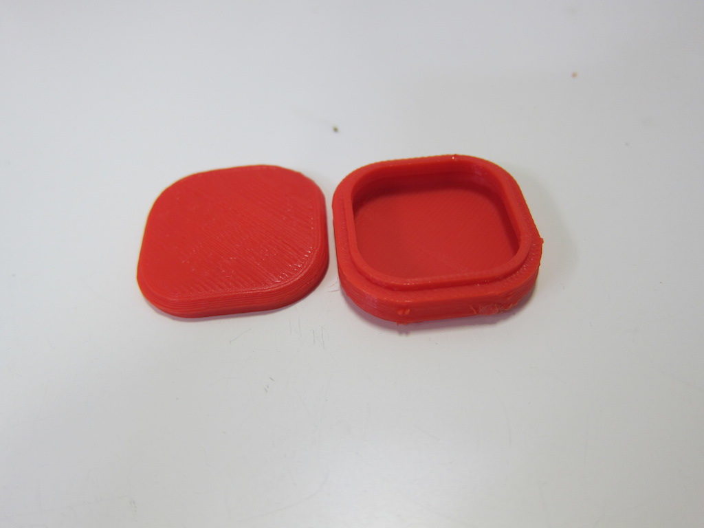
Well, that gave me reasonably good results on the very first try. The top fits, but might actually be a wee bit too tight. I’ll try again, increasing clearance to 0.5. I’ll also see if I can go with a wall and lip thickness of just 1mm, and I think I had the temperature a bit too high, so I’ll adjust that too. A more scientific approach would be to modify just one variable at a time, but I think I can get away with breaking that rule here.

pb_test2

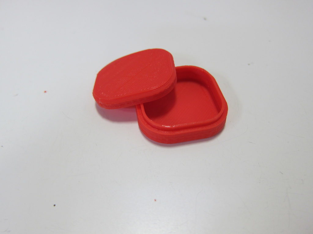
Looks good; the new wall thickness is fine. The lid fits with a bit of wiggle room and no longer snaps in place. For a good friction fit, I think something closer to 0.4 than 0.5 would be about right for the clearance parameter. I’m confident enough at this point to try something bigger: 80x60x25.

pb_80x60x25_042

pb80x60x25

And it works great.

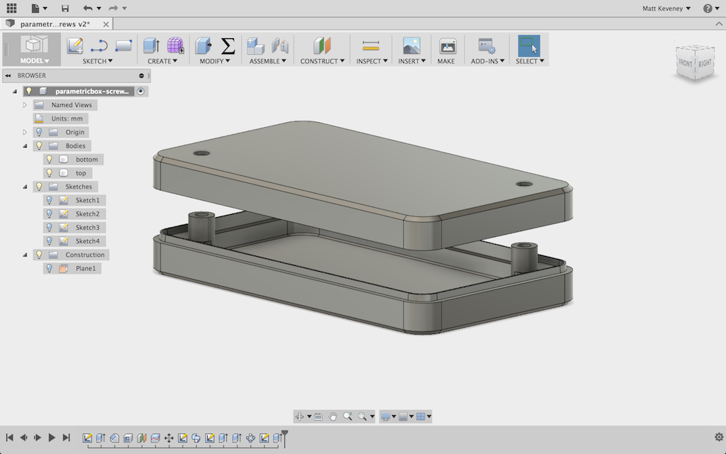
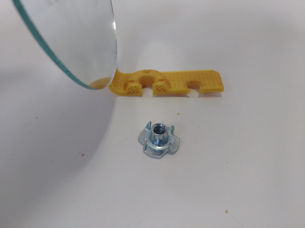
Instead of doing all that work to get a close interference fit, I can just use screws to fasten the box together. I could eliminate the lip altogether and rely on the screws to align the top and bottom, but I’ll keep the lip, modifying the profile so that the mating face slopes slightly inward. Now, the lip serves merely to align the top as it is fastened in place.

pb_slopedprofile pb_slopedlip

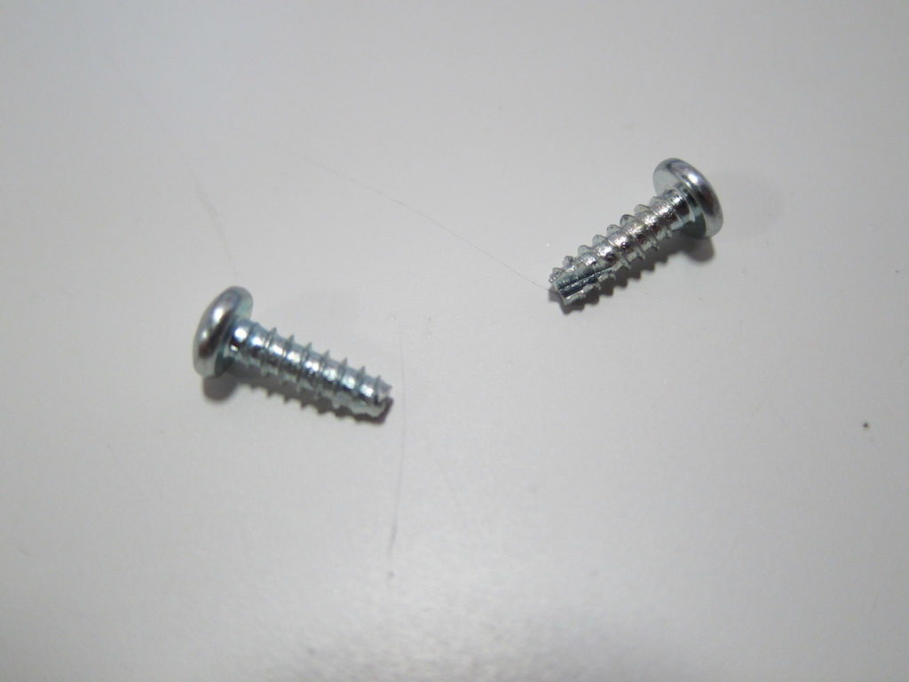
I’ll design for two of these these self-tapping screws in opposite corners of the box. They require a smaller hole in the bottom, where the threads bite in, and a larger hole in the top. If you get the hole sizes right, you can even get away with normal (not self tapping) machine screws.

pb_stscrews

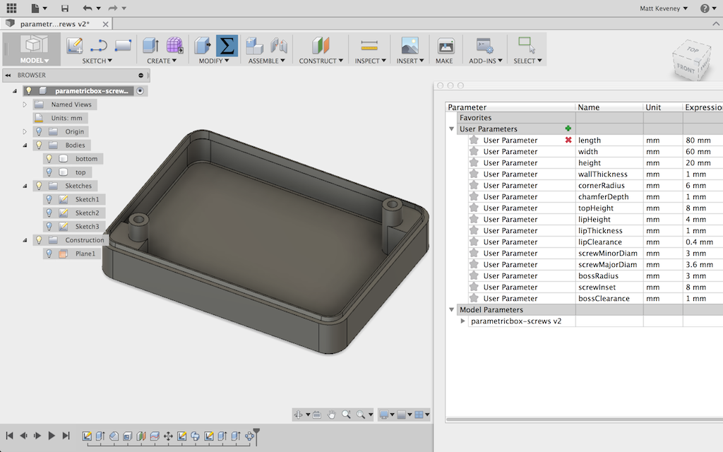
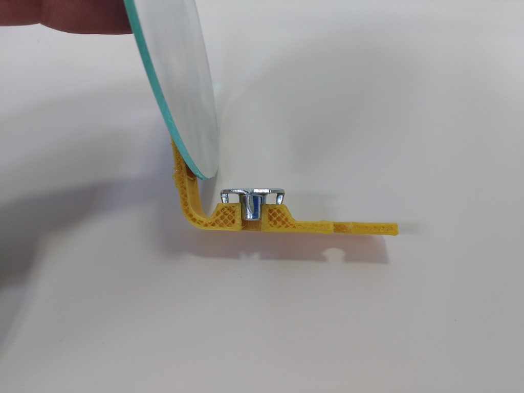
The screws are not long enough to reach to the bottom of the box, so I’ll add a boss for the screw to bite into. Since this boss is so close to the edge of the box, I’ll extend material to the sides of the box in the lower portion. Here are the parameters I’ve set up:

pb_bossParams

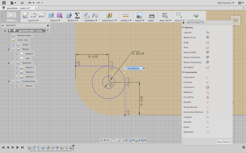
It might be tempting to center the screw right at the center of the curved corner profile, but remember that this is a parametric feature. If the curve radius is made very small, the center would not be an appropriate place for the screw. Instead, I’ll make an independent parameter to fix the screw location relative to the inside edges of the box. This way, I’ll have the option to align the screw with the corner if I like.

pb_boss_sketch

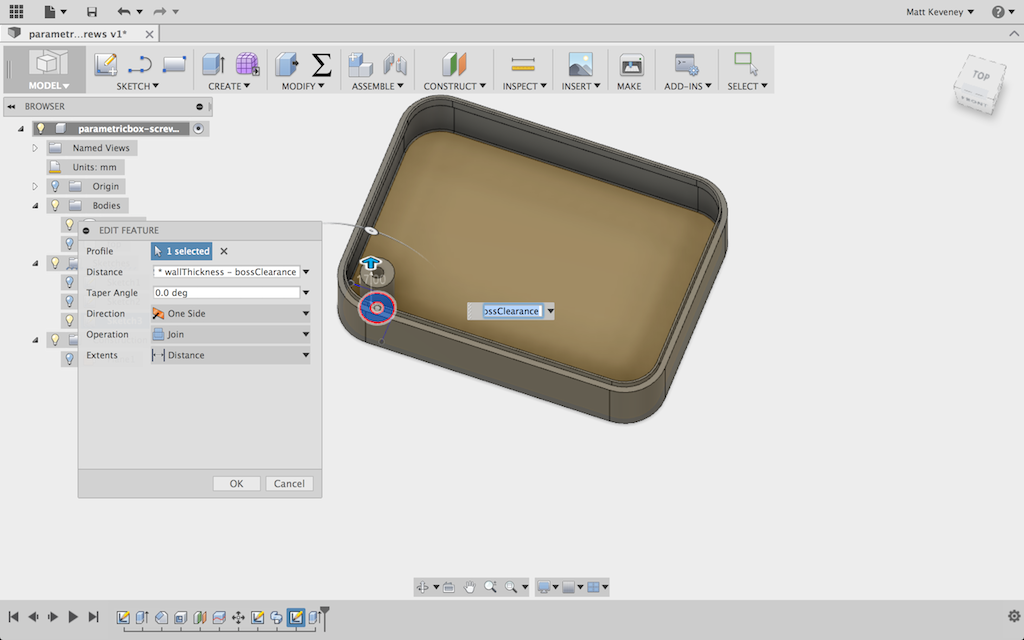
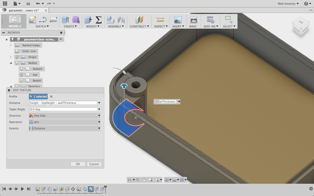
I’ll extrude the boss itself almost to the inside top of the box. I used a formula that didn’t show clearly in the screenshot: height – 2 * wallThickness – bossClearance.

pb_bossExtrude

The reinforcement is carried up to the middle of the lip.

pb_bossReinforcment

Then I use the circular pattern tool to copy the boss and reinforcement to the opposite corner. Another good reason to center my part around the origin.

pb_otherboss

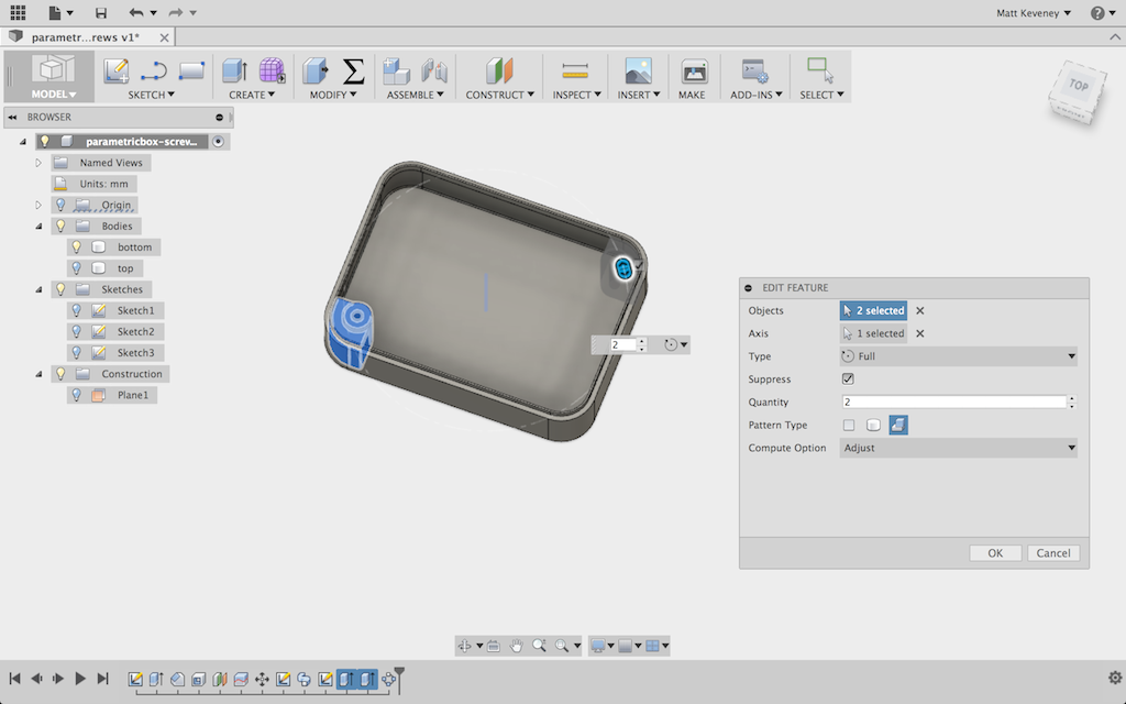
I adjusted the boss-related parameters a bit just to assure myself that they’re working properly. So far so good.

pb_newbossparams

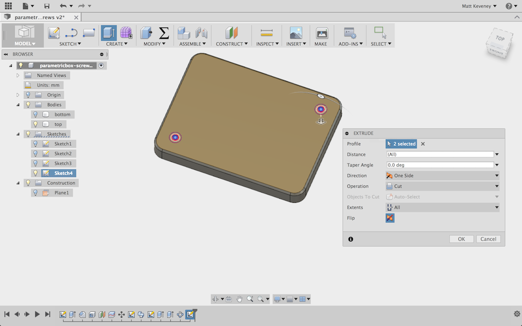
Now, I unhide the top, create a sketch on it, and project the boss perimeters onto the sketch. Note that I’ve projected the outer boss perimeters; not the central holes. This avoids confusion with the clearance holes in the top which have a slightly larger diameter.

pb_top_hole_sketch

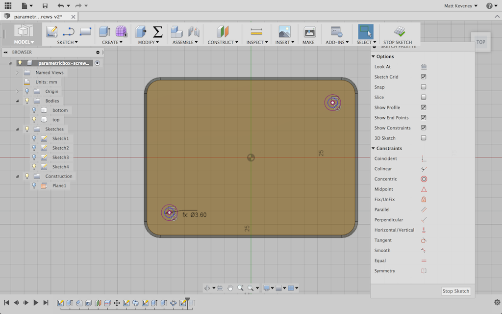
And, finally I use the press pull tool to bore the holes. I hide the bottom first, so I don’t accidentally bore the hole through both parts.

pb_top_holes_bored

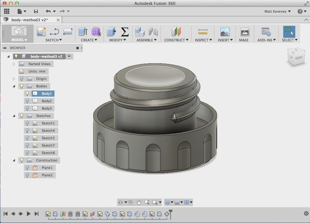
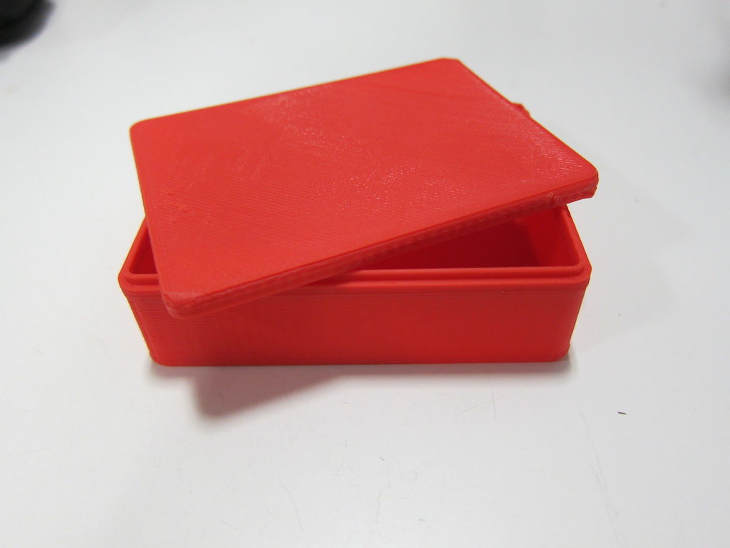
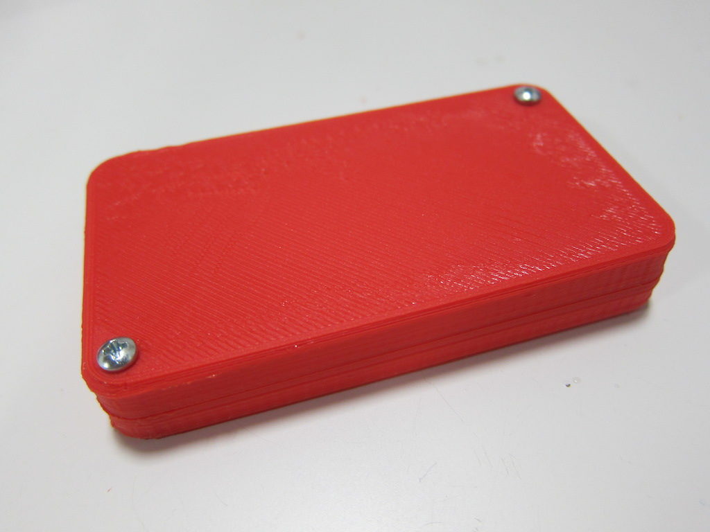
A few parameter tweaks later, I’m ready to print!

pb_holedreadytoprint

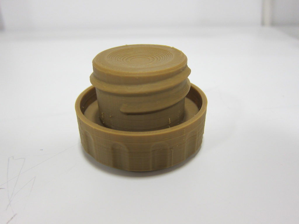
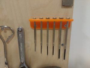
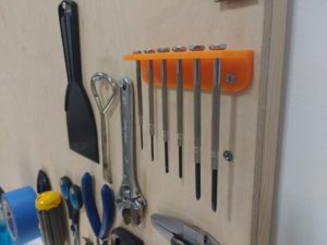
And this is the result.  You may download these models below. I’ve tried to make them as flexible as possible; I hope you find them useful!

pb_withscrews

Click here to download the Fusion360 model files.

Update:

Shortly after publication, I found a bug in this model.  See my follow-up article:

https://www.acemonstertoys.org/fixing-the-fusion-360-parametric-box/


3D print meeting wrap-up, June 13, 2016

We had another good 3D print gathering last night. New members Bosco, Che, and Dan attended; visitor Tony was investigating AMT, and veteran Enric brought along his latest work.

We started with a printer run through for the newbies. Che picked out a cool little Minecraft sword that we found on Thingiverse. It’s compatible with Lego characters, and is small enough to afford instant gratification.

Dan has begun working with Solidworks recently and has already modeled some impressive parts. He was off and running immediately. Dan, can we convince you to write up a project post with more detail? All members can post on the new AMT website! The parts look really interesting, and the post would be good reading even if the project is incomplete.

3dp-7-13-Dan

Enric as usual brought along one of his recent Arduino projects; LED lights for his roller skates. Enric makes custom cases for the electronics; this one fit neatly right under the skate. Enric, we’d love to see project posts from you too!

3dp-7-13-Enric

While Dan was printing away, the rest of us ducked into the classroom, hooked up the projector and brainstormed about design. I had an idea for a little bracket to hold a mirror behind my old camera so I can see the screen and shoot selfies. We got the design done, but by then it was a bit too late to print it out.

3dp-7-13-f360-bracket

So, I just attempted to print it on my own printer. Unfortunately it got knocked off the build platform when it was about two-thirds done. <sigh> Next time I’ll use the brim feature to hold it on better.

3dp-7-13-failedprint

Still, enough of it printed to enable me to test it out.

3dp-7-13-ontripod

There are a few issues I want to fix before reprinting:

The raised boss in the middle was intended to accommodate a woodworking-style blind nut, so that the bracket could be mounted to a tripod. It has pointed teeth which are ordinarily driven into the wood to keep the nut from turning.

3dp-7-13-blindnut

We modeled slots for these teeth, which turned out to be a bit too small. Holes often have to be enlarged for 3D printing; I thought I’d done so, but evidently not enough. Also, the teeth on the blind-nut aren’t perfectly straight, so they probably require a bit of wiggle room.

3dp-7-13-nutdoesntfit

We modeled a simple hole in front to mount the camera with a screw, which I immediately found annoying. A knob would be much more convenient, preferably one that’s somehow captured with the bracket so it doesn’t get lost.

But, the biggest problem is that the geometry turned out to be all wrong. When the camera is framed properly, the mirror is hidden behind it. If I turn it enough to see the screen, the camera points at my bellybutton.

3dp-7-13-hidden

3dp-7-13-bellybutton

So, it still needs a bit of work. Maybe it would work better if the mirror was positioned to the side of the camera rather than above it…? Anyway, I’ll keep after it and post an update.

-Matt

A 3D printed replacement part

I dug my camera tripod out of storage the other day only to discover that one of the knobs has escaped. A great chance to use a 3D printer for something more than a ‘cereal box toy,’ as Hugh puts it.

tk_missing_knob
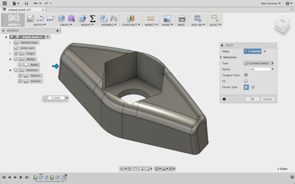
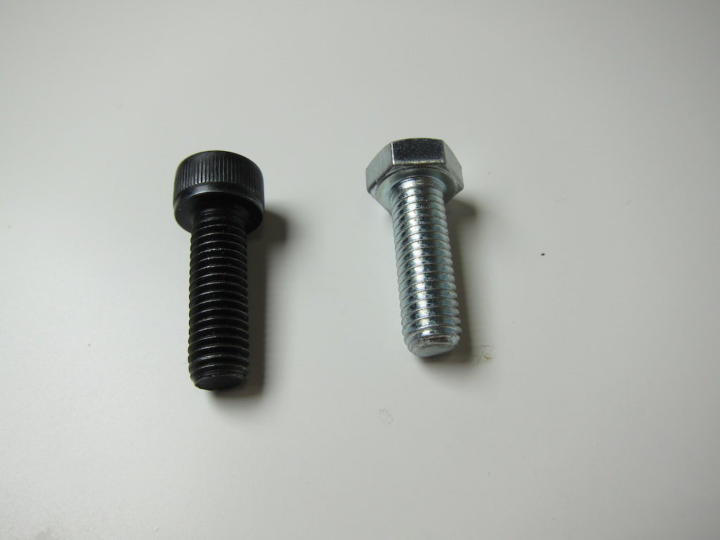
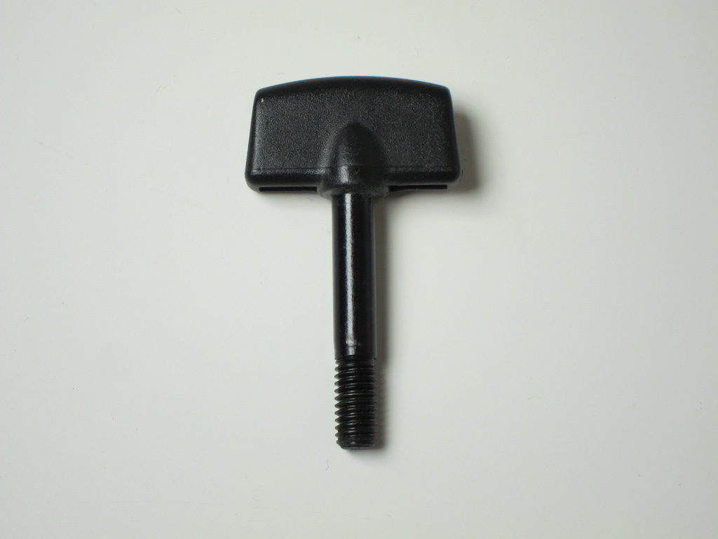
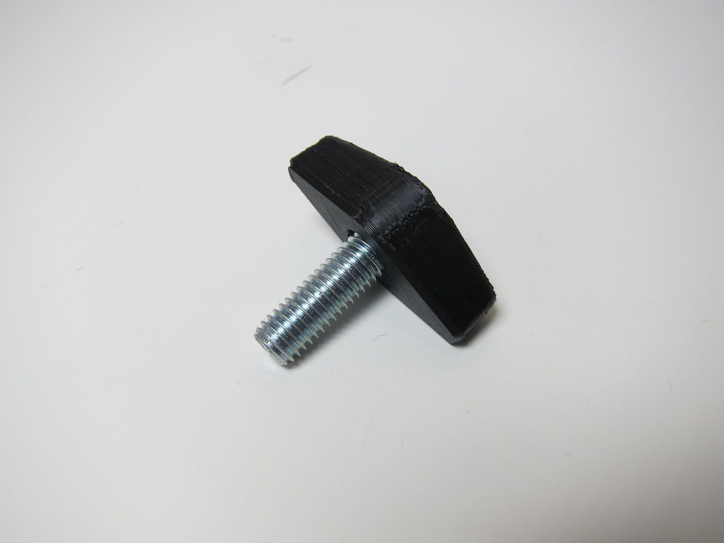
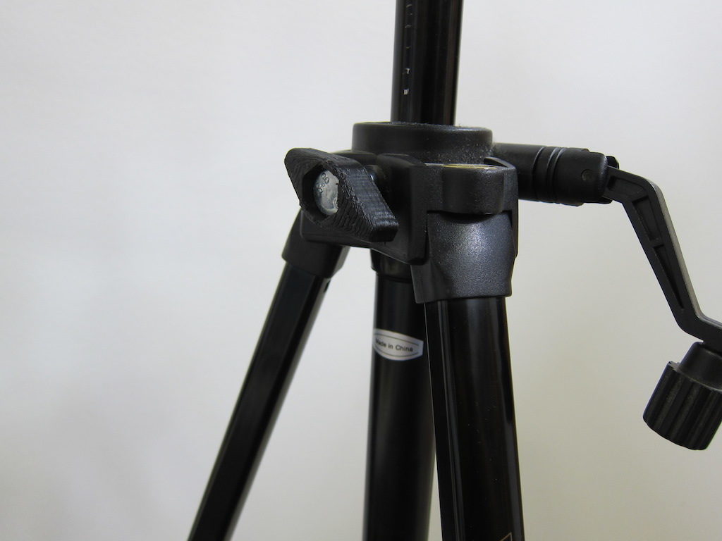
I rooted around in my Box O’ Loose Screws and found a bolt that fits. Unfortunately it’s a cap-screw type, and I was afraid my knob would slip and wear loose over time. So, I went to the hardware store and found an equivalent with a hex-head. I thought I might just be able to find a star-knob while I was there, but this turned out to be a metric size (M8). The head of my new bolt is just under 13mm across the flats, so I’ll start my design around that.

tk_two_bolts

I’m thinking I’ll make a plastic knob that a conventional bolt fits into. Since I’m making my own, I can also try to duplicate the style of the existing knobs on the tripod.

tk_paper_sketch

First I create a sketch on the XZ plane with the hex head centered. I create a hole for the threaded part to fit through; a construction circle to which I can align the flat sides of the ‘wings,’ and then the wings themselves. This sketch describes three distinct profiles: the innermost hole; the hex hole, and the wings. Fusion 360 highlights these profiles as you hover with the mouse; in the following screenshot, the hex profile is highlighted.

tk_sketch1

I extrude the outermost profile upward to create the wings.

tk_extrude1

And I extrude the outermost and hex profiles downward slightly to create the flat part that traps the nut. This also extends the wings downward.

tk_extrude2

I could stop right here and have a functional part. If I was in a hurry that’s what I’d do, but I’ll keep going just so I can illustrate a few more Fusion 360 tricks.

On my tripod’s other wing-knobs the side profile is slightly rounded on top, and has ends that slope inward slightly. Retaining this design detail might make my new part look more like it belongs.

tk_existing_wingnut

I’ll create another sketch on XY plane for this. Note that this sketch plane bisects the current body; that’s OK. I first project the intersection of the top and bottom face of the body into my new sketch, then hide the body. Then I select the projected lines (the purple ones) and click X to convert them to construction lines. Now I can draw the rest of the sketch, using the construction lines to guide my work.

tk_sketch2

Then I turn the body back on and extrude this profile, using a symmetric direction and the intersect operation.

tk_intersection

Now, I use the fillet tool to round the edges a bit. I’m a big fan of the fillet tool for parts that get handled frequently; it really makes a big difference in the feel of the part.

tk_filletted

I’m planning on printing this oriented with the hex hole upward. If I fillet the bottom edges of the part, I may get sloppy results, since the start of the fillet curve is over our overhang limit. I’ll simply use the chamfer tool instead.

tk_chamfered

Let’s print it out! I generally use two perimeters and four layers top and bottom. In this case I’ll use 25% fill. I really only use three fill settings: 15%, 25%, and 40%. I don’t think the percentages reflect the density of the part; 40% is nearly solid.

tk_printing

It works!

tk_assembled
tk_inplace

Terry and Claire’s first print!

Terry and Claire’s new printer is working!  Terry writes:

Hi Matt.

I spent a bit of time getting our printer in order and it is now starting to spit out completed prints.  The adhesion to the bed is good so I think it was a matter of getting the bed level.  
I disassembled and rebuilt the hotend to stop the filiment leak you noticed.  Once I tightened everything up it got much better.  I’m still seeing a large temperature drop while printing but the print came out fine.  I also switched to printing from the microSD card.
I noticed the threaded rod and nut system was getting a little loose and tightened it up.  
Success!
firstprint
Congratulations Terry and Claire!  It’s been fun to watch your progress!

Modeling custom threads in Fusion 360

At our 3D print meeting on May 16, a few of us discussed modeling for 3D printing. We used Jill’s thermos stopper as an example to be reproduced using Fusion 360. The original stopper was made of formed stainless steel (I think), and had shallow external threads extending about 1 1/4 turns. The thread cross-section was a graceful curve, making it easy to clean, and probably easy to manufacture.

Most of the modeling was straightforward, but the non-standard threads presented a challenge. This post makes good on my promise to follow-up on the subject. I’ll also take a few side trips to share some of my habits that I think make the modeling process easier. You’ll get more out of this post if you’re at least somewhat familiar with Fusion 360. Their website has excellent online tutorials.

Before continuing, I should point out that Fusion 360 does have a thread tool capable of creating a number of thread forms by simply entering measurements in a dialog box. It supports a lot of thread types and it’s definitely the way to go if you’re working with standard fasteners or if a standard thread form will do. For a model to be 3D printed complete with threads, be sure to check the modeled box. The threads will have to be fairly coarse to get reasonable results on our FDM printers. Un-modeled threads merely communicate the design intent to the manufacturing team. This saves a lot of space in the design file, allows for much faster rendering, and is appropriate when the threads will be cut by a tap or die as a secondary manufacturing step.

But on with our example. First off, we need something to apply the threads to, so I’ll take a detour to re-create the basic stopper model. In fact I’ll illustrate three different ways to do it. (I did not save the original model we worked on, so these dimensions are just the best I can remember.)

Stopper body, method 1

The first technique I’ll show is perhaps the most intuitive to a newcomer. Folks who’ve used Sketchup or another simple modeling tool may find this familiar.

First create a cylinder, specifying the dimensions of the large end of the stopper.

stp-m1-outer

Then create another cylinder to the dimensions of the cutout portion where the gasket seats, and logically subtract it from the first part.

stp-m1-lip

Finally, create a third cylinder, the dimensions of the inner portion of the stopper, and join it with the first body. Fusion 360 chooses join or cut operations by default if the new volume touches or intersects an existing body.

stp-m1-inner

This is my least-favorite method of the three described here, since the dimensions are scattered among the operations. To make a change or even just view a measurement, we have to search through the operation history (at the bottom of the screen), opening the steps one-by-one. Still, the results are equivalent, so if it seems intuitive and comfortable to you, by all means use this technique.

Stopper body, method 2

Start the next method with a sketch on the XZ plane containing 3 concentric circles. These are dimensioned to the diameter of each section. Fusion 360 by default arranges positive Y up, positive Z toward you. Most 3D printers consider the bed to be the XY plane, with Z being the vertical axis. This is not a big deal, since we can rotate our part before slicing, but it might be confusing to a newcomer.

stp-m2-sketch

Next make three extrusions using the push-pull tool. The first extrusion is the innermost portion of the stopper.

stp-m2-inner

Fusion 360 automatically hides the sketch after this operation, so we need to unhide it again (click the light bulb in the browser). Then select the next profile outward and pull to the level of the stopper below the gasket.

stp-m2-mid

Finally select the outermost profile and pull to the depth of the outer section.

stp-m2-lip

I like this technique a bit better, since the three diametral dimensions can be viewed together and edited just by opening the sketch. We still have to go hunting to find or change the extrusion heights. I should note however that we can make this hunting somewhat easier by renaming the operations (right click in the operation history). This helps with the first method as well.

Stopper body, method 3

The final technique uses a single sketch in the XY plane which describes a radial cross section.

stp-m3-sketch

Then we create the solid with a single revolve operation.

stp-m3-revolve

While this might seem the most abstract of the techniques, it’s my favorite since all the dimensions I might want to change are located in a single sketch. I’ll use this version in the remainder of the article.

The threads

Now for those threads I keep promising. We’re going to create a profile and sweep it along a helical path.

Unfortunately Fusion 360 doesn’t seem to have convenient way to draw a helix. My first thought was to write a Python macro, but that’s probably because I’m a software engineer and If you own a hammer, every problem looks like a nail.

So, I spent a bit of time exploring other options and discovered the coil tool. This is obviously handy for modeling springs, but we’ll use it just to create our helical path and then hide the coil forever after. It turns out we actually need two parallel helices; the second serves as a rail to guide our sweep operation.  Without the rail, the profile may twist while it sweeps along the path.

But before we start, we want our coil to have the same diameter as the inside portion of our stopper, so let’s go back into the stopper sketch and give that dimension a more meaningful name. First we open the sketch and double-click the dimension.

stp-thr-dim3

We see that it’s labeled d3. Then open the change parameters dialog, browse to dimension d3, and rename it inner_radius.

stp-thr-innrad

Now, if we double-click the dimension in the sketch we see that it has been renamed.

stp-thr-sketch-innrd

Create a new work plane, parallel to the XZ plane but offset upward to the lower extent of our threads (25mm).

stp-thr-construction-plane

Hide the stopper body for now, just to get it out of the way. Then create the coil on the work plane we just added, centered at the origin. Use a triangular section, positioned on the inside of of our specified diameter, with the remaining settings as shown.

stp-thr-inner-coil

Note that the diameter is set to inner_radius * 2. Now, if we modify the dimension in the original sketch, the coil will automatically adjust to match. Unhide the construction plane, and create another coil identical to the first, except position this one to the outside.

stp-thr-outer-coil

Select the work plane again (unhide first, if necessary) and create a sketch on it. Click the home button to get a perspective view, and select Sketch > Project/include > Include 3D geometry. Now click the outer edge of the outer coil. You’ll see a purple line appear.

stp-thr-rail-helix

Hide the outer coil, and select the outer edge of the inner coil. Another purple line appears. Hide the inner coil.

stp-thr-path-helix

Whew!  All that guff was just to produce those purple helices. Note that even though the curves are hovering over the sketch plane, they still belong to that sketch. Close the sketch and unhide the stopper body so you can see how these curves look in context.

stp-thr-helices-context

Hide the stopper body again, select the inner helix and create a construction plane along the path. Drag the plane to snap to the lower end of the helix, and finish the operation.

stp-thr-profile-workplane

Drag the view around a bit, and notice that the plane is not quite vertical but is perpendicular to the helix. This is important for the upcoming sweep operation.

stp-thr-profile-perp

Select that plane and create a sketch. Then draw the thread profile and close the sketch.

stp-thr-profile-sketch

The sharp eyed will notice that the left vertical line in my profile is offset slightly left of center. This forces that edge of the profile to end up inside the inner cylinder. Otherwise, only the center point of this edge would actually touch the cylinder, since the entire plane upon which it is drawn is tilted slightly from vertical. Offsetting slightly inward avoids intersection problems when we later join the sweep to the stopper body.

Now, finally, unhide the stopper body and select the sweep tool. Select type: Path + Guide Rail, then choose the new sketch profile, the inner helix as the path, and the outer helix as the rail. Turn profile scaling off, unhide the stopper blank, and select operation join.

stp-thr-sweep

We’ve added our custom thread!

stp-thr-altview

Here’s the model after a few more cosmetic operations.

stp-thr-cosmetics

Of course I know you wouldn’t believe a word of it unless I printed one out, so here you go.

stp-printed

I hope you’ve enjoyed this article. Please leave your feedback below, including any other modeling questions you might have. Does anyone have any interest in a modeling class for 3D printing? If so, give me some ideas for what it should include!

-Matt

3D print meeting wrap-up, May 30, 2016

Just two guests tonight.  Maybe holidays that happen on game 7 of a Warriors series aren’t the best choice for meetings!

But we had fun anyway.  Terry and Claire were back with their Prusa i3 kit. After a bit more tweaking and leveling we did manage to print a test block, but our success was marred by a slight leak in the nozzle.  I sent them off with instructions for cleanup and repair, so I think we can expect cool results very soon.

Claire looking goofy... Terry always looks like that.

3D print meeting wrap-up, May 16, 2016

We had a great turnout at tonight’s 3D print meeting!

Welcome newcomers: Alex, Kevan, Efrem, Nate, Terry and Claire (did I miss anyone?), along with returning guests Enric and Jill.

It was a busy night with a lot happening. We demonstrated a print on the Replicator II, printing a key-holder Nate found on Thingiverse. I brought my delta and demonstrated a simple print on it as well, to show how the workflow differs for the open-source toolchain.

The cool key holder shelf
The gang, hanging out

Next we discussed design a bit using Jill’s water bottle stopper as an example to model in Fusion360. That’s a great example since there are so many ways to do it. Watch for a future post on how to model the thread.

Modeling thoughts
Modeling thoughts

Enric brought along a few of his electronic-project enclosures for show-and-tell. He’s also been doing some interesting experiments with light-pipes for wearable-electronics.

The highlight for me was Terry and Claire’s new Prusa i3 printer! They got a very inexpensive kit from AliExpress for under $200!, and had just finished assembling when they brought it here. After a bit of testing and fiddling with wires we had it mostly working. Unfortunately it was getting a bit late so had to stop a few inches short of that exciting first print. I sent them off with a list of things to do, after extracting a solemn promise to send us pictures.

Claire and Terry's new printer!
Claire and Terry’s new printer!
Terry and Claire shooting trouble

I was very impressed with the quality of the kit; and the price was better than you could do sourcing the individual components yourself. According to Terry, shipping was very fast. I got the impression the instructions were a bit on the thin side, but that’s what we’re here for.

5/19/2016: After I wrote this, Terry was good enough to send me a copy of the digital instruction manual that came on an SD card with the kit.  I must say, It looks a lot better than I expected: 

Prusa kit manual example page

Terry and Claire: we’d LOVE for you to write up a review of the kit and your experience building it. I always tell folks how easy it is, but the opinion of a power-geek like me simply can’t be trusted. If word gets out that normal well-adjusted folks like you can do it, maybe more would give it a try.

-Matt

South Pointing Chariot

A South Pointing Chariot is a vehicle carrying an indicator that always points South. As usual, there’s a good article on Wikipedia.

While the device was mentioned in a number of ancient Chinese texts, no design or construction details have survived.  My model (like many others) assumes that a differential gear train was employed.

It’s been a fun project, but it’s a bit too difficult to assemble, and the wheels need work.  watch this space for an updated version, including full CAD source files.

-Matt

3D print meeting wrap-up, May 2, 2016

Just two folks attended tonight’s 3D printer meeting; both were newcomers. Welcome Joe and Julio!

Both came armed with Fusion 3D models. I won’t divulge the details, in case they embody valuable trade secrets, but it was exciting to see such advanced preparation.

We did the usual walkthrough on the Replicator II. Joe had to leave early, but assures me he learned a few things. Julio stuck around to see his first part printed. We selected the simplest of three that he brought along. I suggested a few modifications to the other parts that would likely make printing more successful.

I brought my delta for demo purposes, and also brought my latest project for show & tell: my south-pointing chariot. Expect a more detailed writeup and perhaps a short video clip later. I’ll bring it to Thursday’s meeting too.

-Matt

3D print meeting wrap-up, April 18, 2016

We had another great turnout for the 3D print design meeting. Eight folks in all. Two newcomers, Jill and Arun (Welcome!); two veterans, Enric and Don; two special guests from MadeSolid, Lance (and another fellow who’s name I neglected to write down); and Sean and myself.

Sean showed off some of his cool work, and answered lots of questions as always. Jill and I walked through a simple Fusion 360 project: A small screwdriver rack for my tool-board.

I forgot to bring the screwdrivers along, and was afraid the holes might be a bit too tight. Sure enough, when I got back to my shop I found out they were. Just enlarged them a bit and reprinted on my own printer.

This only took about 20 minutes from a blank screen in Fusion 360 to starting the print (which took almost an hour). Designing something like this can be fun and easy once you get your feet wet with a modeling tool. Come to the next meeting and see how much fun it is!

-Matt

printing bracket at AMT
The finished bracket, rev 1
Oops! The holes are too small.
printing new version of bracket
bracket front view
bracket front view
bracket side view
bracket side view