
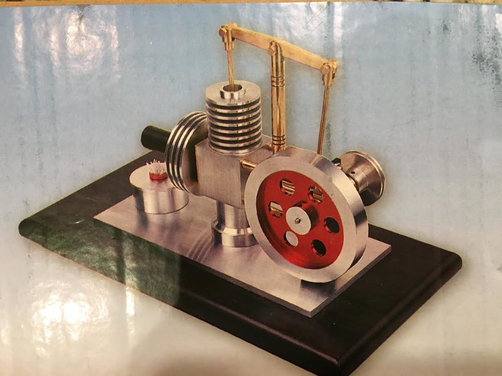
Once upon a time, I bought some plans and materials for a small Walking Beam Stirling Engine. I have seen lots of small home built steam, heat, and even internal combustion engines over the years and thought it would be fun to make one.
Here’s a picture of what it should look like when it is finished
Well, the box with the plans and materials has sat in my garage for 5 years now, and I think it is time to finally get started. So I have made a deal with myself to make a part each week until it is done.It would be an opportunity to really get to know our lathe and milling machine at AMT. I have mostly used bigger, more powerful, and more rigid machine tools at The Crucible, and Techshop. Working with the smaller, lighter machines we have at AMT and how to deal with their limitations will be a learning experience.
This week I was able to make 2 parts.
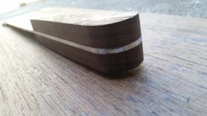
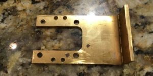
First I made the bracket which supports the crank arm and flywheel shaft. It started out as a 3mm thick brass plate. It needed to be cut to size and shape, and have some precisely positioned holes drilled. It also needed to be bent with a 90 degree angle. It took a bit of thinking about what order to do the operations. The holes need to be a precise height above the platform it all mounts on, and I know that the bend was going to use some of the material up in the curve, but I didn’t know how much. So I decided to “square up” the plate, then bend it, then cut it to shape, and finally drill the holes in the right spots. I used the milling machine to shape, the vise and a hammer to bend, and finally the drill press to do these operations. Here’s a picture of the finished part.
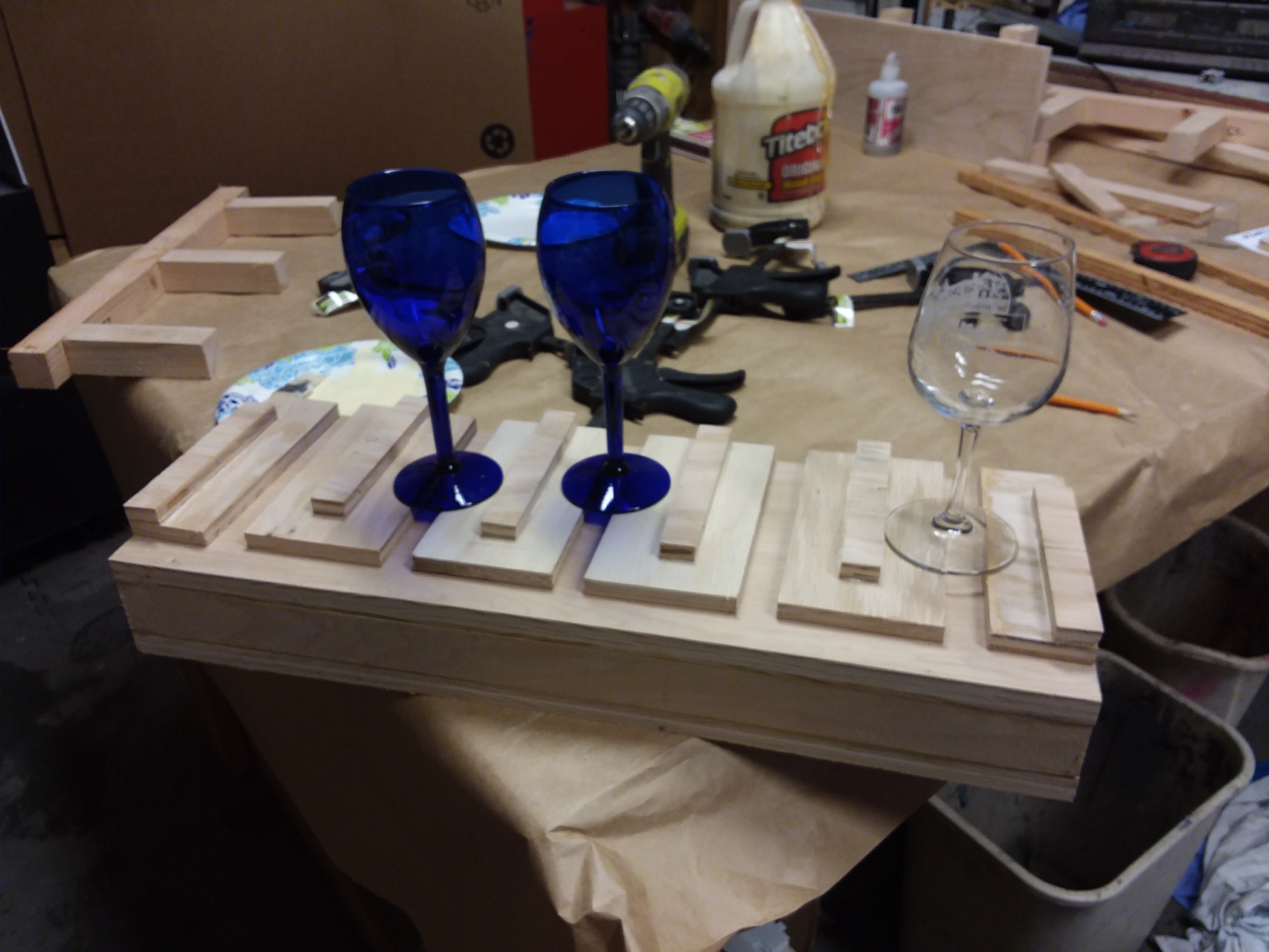
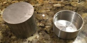
The other part I made was the fuel tank, which is basically a little aluminum cup with a lid and a wick to burn alcohol. This started out as a round bar. On the lathe I “faced” or flattened one end, turned it around, hollowed out the inside of the cup, and finally turned the outside to the final dimensions. Here’s a before and after picture.
So far I am pleased with the results. In hollowing out the inside of the cup I learned that those carbide boring bars that came with our lathe are just too flexible to be useful. But a good sharp HSS tool was able to make clean cuts.
Next I think I will try to make the cylinders. The deep cuts to make the cooling fins look like they may be a challenge to get right.

AMT is thrilled to be partnering with Hoover Elementary School in Oakland for a community benefit project. With the help of a team of engineering students from UC Berkeley, AMT will provide the community, space, tools, minor funding and mentorship to help create a truly edible community garden at the school. Our partnership will focus on signage, other usability aspects and will include developing classroom content to engage students in the design and build process.
We will be starting to meet weekly for design co-working in the space during the last week of November. We are part of a larger team doing a complete garden build out lead by the Hoover Elementary garden steward Wanda Stewart. We are actively seeking mentors, educators, and makers who are excited to get involved and contribute to this project.
![]() All kinds of support are welcomed: whether you are interested in documenting, building, developing classroom content or designing builds in the garden.
All kinds of support are welcomed: whether you are interested in documenting, building, developing classroom content or designing builds in the garden.
Contact @crafty on Slack to get involved! Or email [email protected]

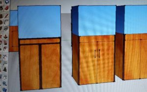
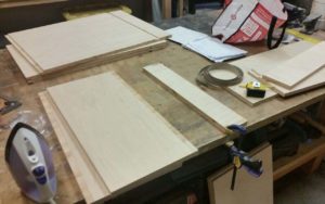
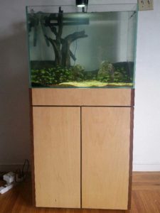 This is an aquarium stand that I built at Ace Monster Toys. It is made of maple 3/4 plywood and walnut edge banding. I used the old craftsman table saw and the ryobi router table to cut and shape the parts. If I had to do it over again I would use the CNC router. It would be far far safer, faster, and the results would be cleaner and more square. I would probably also use strips of 1/8″ walnut instead of the iron-on edge banding, because it would be much more durable and age better. After designing the piece in sketchup, I made some test pieces to practice edge banding on. The idea is to use the edge banding to hide the screws and the ugly edges of the plywood. It was a challenge to cut up the 4×8 sheet of plywood with a handheld power saw. A panel saw would have been better. After getting the pieces small enough to fit in my car, I took them to AMT and cut them to size on the table saw. The problem was that, even with my own brand new blade, the saw would not cut perfectly square, and the measurements on the fence were not accurate. It was very frustrating and the results were not perfect. I used the router table to cut dadoes and rabbets where the walnut strips would go. After assembling the box, I used an iron to iron on the walnut edge banding, which I trimmed with a razor. At this point I took the stand home for finishing, and added some wheels. The stand contains my canister filter and CO2 tank. I am very happy with the result, but if I had to do it over, I would use the CNC.
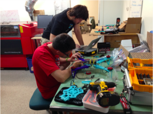
I was working on this project with a few friends, all of us were absolute beginners when it comes to quadcopters. Since the construction can be split into subtasks it was easy to keep everyone busy, between soldering cables, tweaking the 3D printing settings, or configuring the flight controller. Team work is fun, especially when you spend several hours focused on the same project. Everybody learned something along the way.
Because we wanted to learn about how quadcopters work, we choose to build our own instead of buying one ready to fly. It’s easy to find some sample designs on Thingiverse, for example. We choose to start with the crossfire 2 and customize it a bit to better fit our parts, usage, and to cope with our really poor pilots skills (because crashing means re-printing parts.. And we crash A LOT! :)).

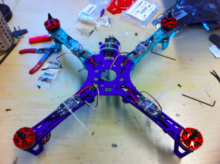
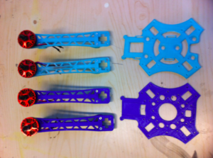
The crossfire 2 comes with a very detailed instruction guide. For most parts you just need to follow the guides, and some parts are specific to the components you choose. We picked the PixHawk flight controller for example (of which the project’s codename is a pun). Overall it was rather easy to get everything assembled. Here you can see the quadcopter with half of the body assembled, the four arms, and the ESCs (Electronic Speed Controllers).


I’d seen the youtube video from the Backyard Scientist guy and wanted to try that project myself.
Asking around for dead microwaves via the AMT mailing list produced more than I needed, but extra is always welcome. I was able to take the microwave apart without killing myself.
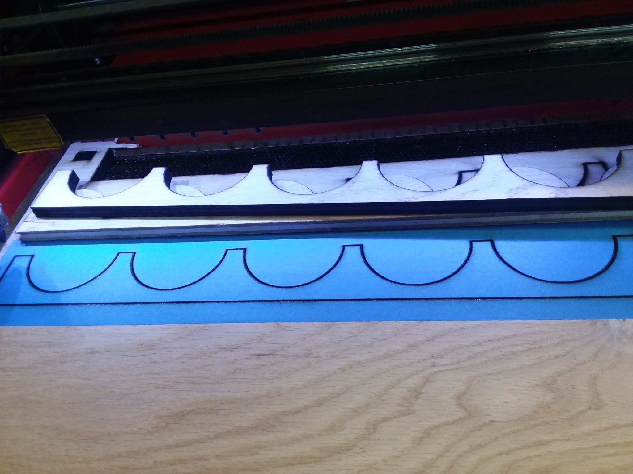
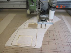
I have ideas of doing this in front of people as a science demo so I wanted a setup that was contained, portable and safe. I designed some CAD files to make a setup so that it would hopefully not kill anyone and started cutting the pieces out of plywood on the big CNC machine.
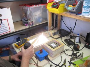
After cutting the parts out on the CNC it was a matter of glue and assembly. The idea is to have an airtight chamber so I could add CO2 at some point to cut down on the fire.
Testing was done on the workbench and lo! I was able to make sparks with the high voltage of the microwave transformer. The trick is to have the two sides with the grain and have the board wet when you are burning it. Took me awhile to figure out that a dry board is not going to happen. Doh!

It creates smoke and you want to do it in a well ventilated area.

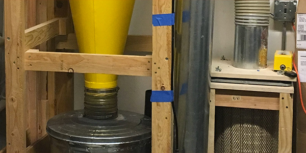
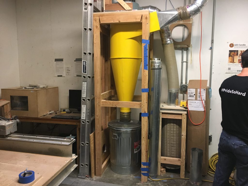
We have a new dust collection system!
Our previous system (which used to live in the closet) has been replaced and we now have a cyclone dust collector.
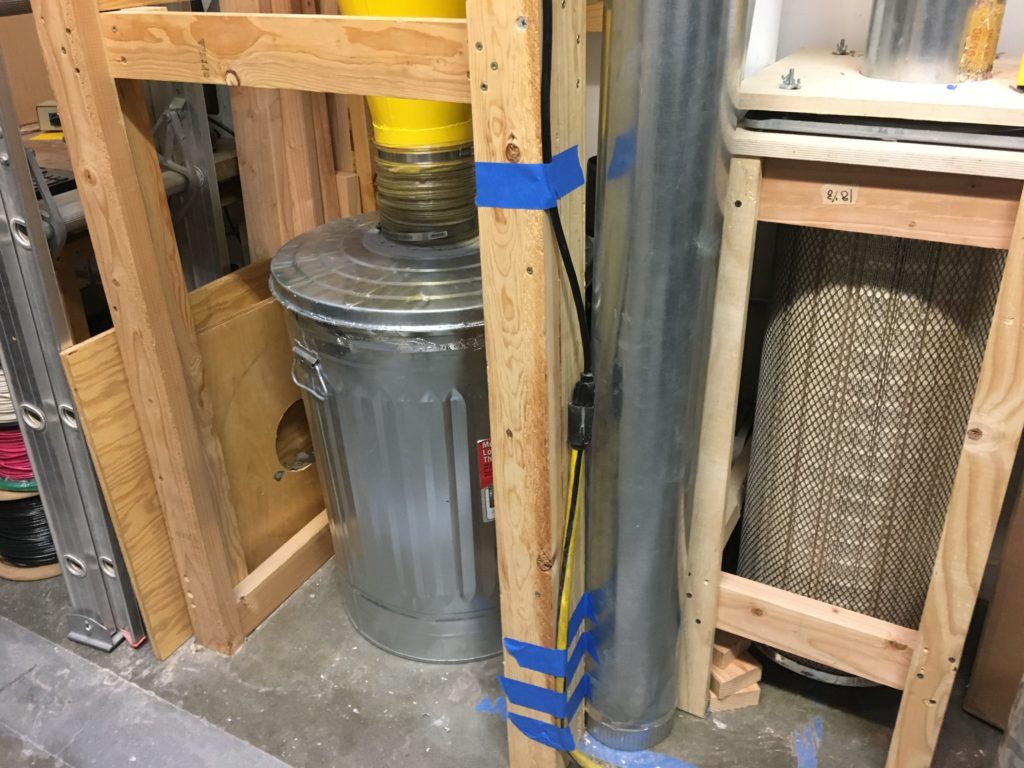
The cyclone lives in the metal shop and is hooked up to the ducts in the workshop.
To turn it on, currently you need to plug it into its extension cord. Look for the blue stickers on the right side of the cyclone:
We are interested in your feedback regarding this new system.
You can use our equipment feedback tracking with the asset tag AMT140 to report issues.
Ping us ( @fitzhugh or @pierre ) on slack in the #workshop channel if you have questions about this system!

Thanks to the growth in portable battery options we can hack those “power banks” to make portable, rechargeable five volts power sources for your own projects.
We will be be hacking and comparing two different products that output five volts – a nicely packaged and made external battery pack for older Apple stuff and a new cheapie 18650 powerbank.
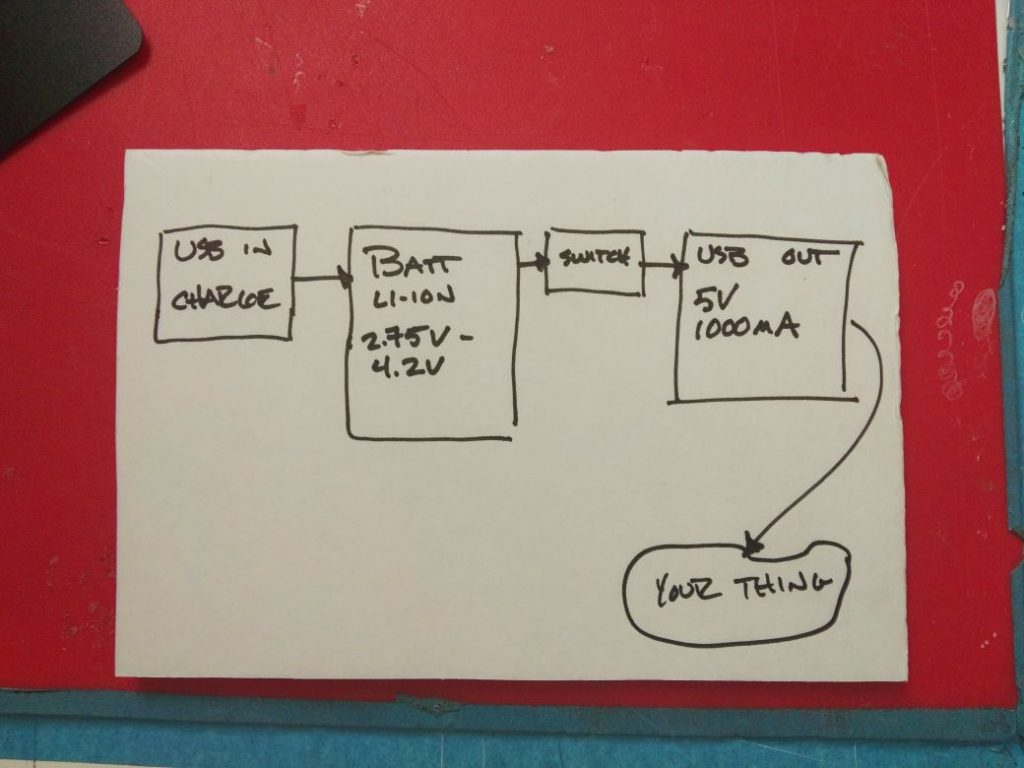
Both products are basically the same. It’s a lithium-ion battery with a USB charger on the front and a boost on the back to output USB standard five volts. Some differences – the Apple power bank thing has an LED gas gauge to tell you how much charge it has and only starts outputting when you press the button. It needs that manual button press to start feeding your project the five volts. The cheapie 18650 powerbank does not need a button press – it’s switch is automatic as soon as you put a load on it, five volts are coming your way. Also the Apple power bank has some battery protection circuitry in it to stop you from draining the battery to the point it’s damaged internally. The 18650 powerbank has no such protection and you can kill the battery if you drain it all the way and then some.
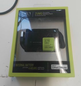 Looks mighty pretty in it’s packaging, this was originally designed to be used with Apple products that had their original proprietary 30 pin socket. Now that Apple has switched to a different proprietary socket everyone had to go out and buy new powerbanks, cables, etc. Look on ebay for deals on stuff like this where time has moved on.
Let’s 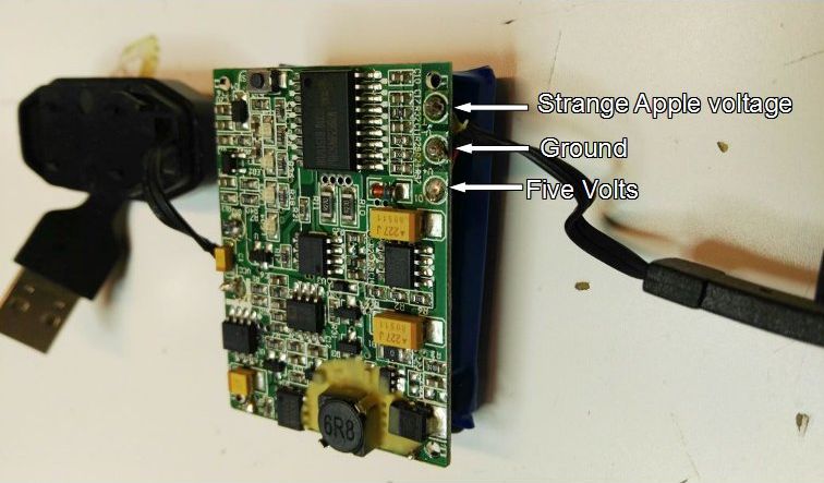 open up the nicer power bank. Grab a thin blade screwdriver and go to town. This is an external charger that is rare in that it has a built in USB cable, not a micro socket you plug a cord into. Designed to feed five volts into the original Apple proprietary socket it is out of favor as Apple has switched to a different proprietary socket. Still, five volts is five volts. After prying off the shell with a screwdriver we can see the output side has three different wires. five volts, ground and some strange Apple proprietary voltage.
We need to cut the old Apple socket off and solder in our own red and black to the five volts and ground connections. At that point we have a portable, rechargeable power supply that outputs five volts a the push of a button. A little hot glue for strain relief on the USB charging cable and perhaps wrapping it in electrical tape so all the connections are covered.
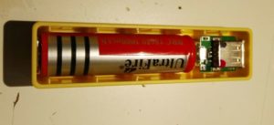
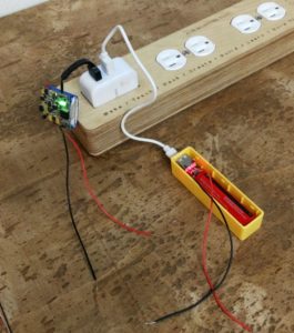
The cheapie 18650 setup is even easier to hack. On USB sockets the two outside wires are the power and on this one, it’s five volts and the right and ground on the left. Knowing that and still putting a bit of color on the socket so we can tell which is which we solder wires onto the exposed connections.
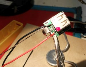
Finally put them all back together again and start charging them up. We now have two sources of five volts for a project, one with a manual switch and LED gas gauge and the other will give out five volts right away, no switch needed. If you need five volts for your electronics project at AMT, come talk to me as I have a small supply of both kinds of powerbank available for member projects.
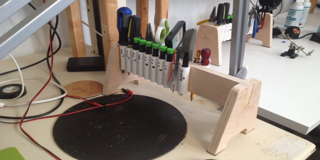
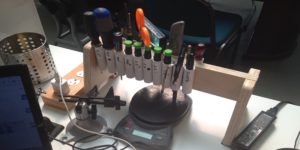 you put a collection of PVC tubing to hold whatever you want to hold. The trick is to have an idea of the tools you want to have on it and lay those out before hand, so you know what kind of tubing and how much you need. Some #6 screws, a drill press, bandsaw and CNC up the wood bits and away you go. Rubber feet on the bottom make sure it doesn’t slide away from you as you reach for that next screwdriver. The tools selected for the rack are based on my own experience in doing electronics and detail work. Precision screwdrivers are a must but so is a regular #2 Phillips and flathead. The #2 and #1 Phillips are probably used more than anything. From there it all makes sense to have enough tools but not too many. You can go crazy on the tool rack but it starts to get too large and would take over the tabletop if you let it. Keep it basic and know what you use.