Category: Projects

The Implausiphone: My Ongoing Never Ending Synthesizer Project

Hi! I’m Devon. Some of you have probably seen me cutting many, many box joints into big plywood sheets in the woodshop, or basking in flux fumes kludging my way through a never ending procession of circuit boards in the electronics section. You may even have found yourself wondering what I was building!

I’ve mentioned to anyone willing to listen that I’m building a synthesizer, but what I’m building might not be exactly what you picture a synthesizer to be.

keytar
Image Source

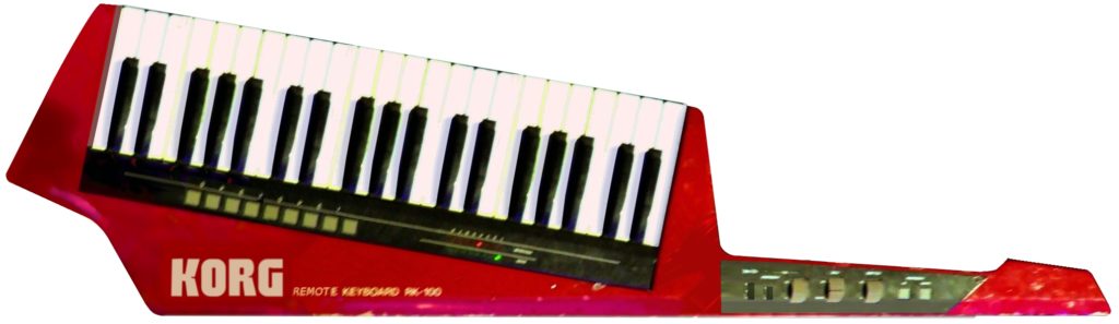
Not that. Not that at all. In fact, my synthesizer doesn’t even have a keyboard.

Here’s what it sounds like.

If you make it to the end I’ll share another little sound bite.

And here’s a picture of it:

Devon's Synthesizer

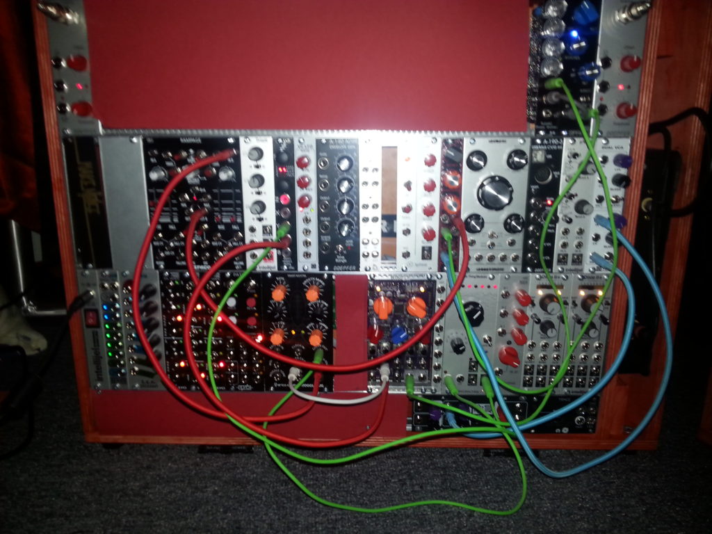
That red stuff is construction paper. The other things are modules, because this is a modular synthesizer. Within the realm of synthesis and auditory exploration, there are a particularly geeky few who are really into analog gear. Even more myopic and esoteric than them is us: the modular synth crowd.

It’s pretty arcane stuff, so I’ll spare you the details, but in essence a modular synthesizer is one which, in contrast to a conventional fixed architecture synth, has no fixed architecture. That’s what those colorful patch cables are for: the signal chain on a modular is created (patched) in-the-moment by the user according the ancient and venerable dictum of “outputs to inputs”. This provides a kind of sonic flexibility that is difficult to achieve through the more regular method: pretty much any output can go into pretty much any input. It’s nuts; trust me.

Modular synths have been around a long time. The first synthesizers were modular. This instrument, if you want to call it that, adheres to a particular format called Eurorack, which is the new kid on the block.

look at this case I built

The Box

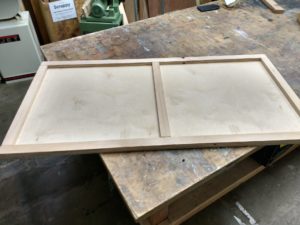
Anyways, all those fancy modules need to go in something. As I live in a tiny apartment, I need to put this thing away when I’m not using it. So I decided to build a case with a lid, which provides the added benefit of the thing being somewhat portable.

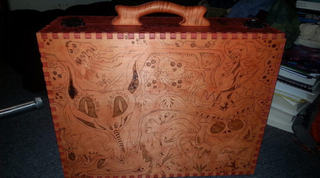
There’s a picture of it! It is constructed from 1/2″ Baltic Birch ply. The handle on the top there is made from curly maple, but more on that later.

Building the box was my first step into Synth DIY (SDIY). And, like everything in life, it took a lot longer than I thought it would.

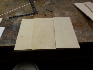
First step was cutting the sheets down to size.You can’t tell from that image there, but by this phase I had already made my first crucial mistake. This mistake would turn out to be a stroke of genius, though (more on that in a minute). The panel saw in the workshop is a thing of beauty — thanks Davey!


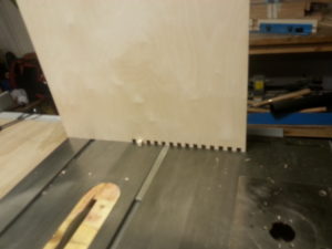
I would like to take a moment to apologize to all the hard-working folk in the coworking space who got to listen to hours and hours of “zhne, zhne, zhne, zhne” as I cut out all those little box joints with the dado blade.


Eventually I got all the teeth cut in, and mostly aligned. I would have to take a file to them to give them enough clearance for the glue, though, since I didn’t really take that into account during the set up. In the background there you can see my trusty box joint jig. It looks sort of like a castle!


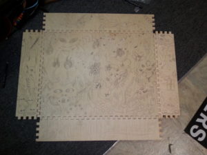
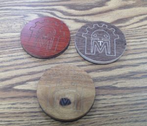
Once all the pieces were cut out, the real work could begin. Most of those drawings were done by my lovely partner and companion Katie, who is a better drawer than me. I contributed though! I arted what would become the top panel here in the time it took her to do the rest of the thing. The design was drawn in with pencil, and then I spent an unbelievable amount of time wood-burning them in with a pyrography pen. I could have got a certificate in the time it took me to do this.


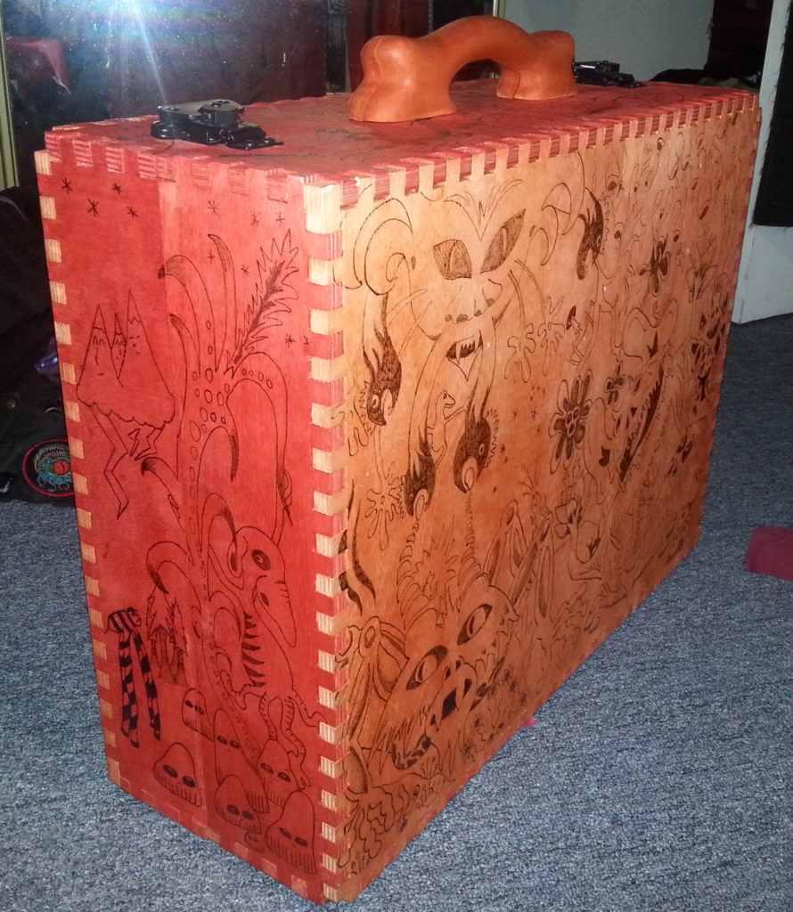
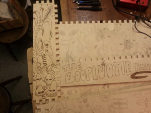
But it was all totally worth it, because it looks pretty sweet. Heres a nice little side-by-side.

Once the wood burning was done, and my burned-to-shit thumb was all bandaged up, it was time to apply the dye. I used alcohol-soluble dyes, which due to the higher rate of evaporation do not cause the the grain to raise like water-based dyes. They’re a bit trickier to use for that same reason, though. I think I did a decent job.


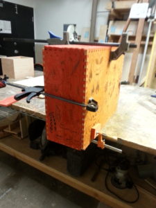
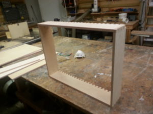
Then it was time to glue it up! This stage was pretty scary, what with there being now dozens of hours invested in the project. Thankfully, I barely screwed it up at all.

Once the glue had dried, it was time to kick it up a notch. I had purchased an assortment of hardware from Reliable Hardware, including a really bogus cheap little suitcase handle. What a shame it would have been to have topped off all my hard work with a flimsy stupid little thing. Obviously, I had to make a handle.

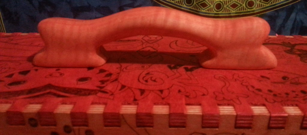
My woodcarving teacher Sheri helped a lot at this point. We designed the shape, and then glued two pieces of curly maple together, with a sheet of thick paper in between them. Once that had dried,  we did a rough cut on the bandsaw, and then I spent close to 10 hours rasping, riffling, and sanding the thing down to the proper shape and luster (and, of course, splitting it back into its constituent halves). During this time I listened to a really interesting book about the history of the Mp3. Then came a coat of that dye, and a nice shiny layer of beeswax and oil finish.  If anyone wants a cheap plastic suitcase handle, let me know.

Remember how I said that I made a big mistake early on that ended up being a blessing? Well, somehow I managed to dimension the whole thing to be two inches too long, and about two inches too tall. Isn’t that hilarious? Now the frame for my rack wasn’t going to fit.

But guess what! That two inches on the side is just enough space to fit in a compartment for a spring reverb tank! Yeah, just like your guitar amp has! Except this reverb tank is mounted vertically. And I managed to find exactly one reverb tank on the whole internet designed for vertical mounting, and that sucker just fits. You can see it on the right hand side of the synth in the picture below.

As for that extra bit of height? I turned that into lemonade too by adding a little mini-row at the very bottom. Currently it’s mostly cardboard, but I will fill it with little handy utility type things.

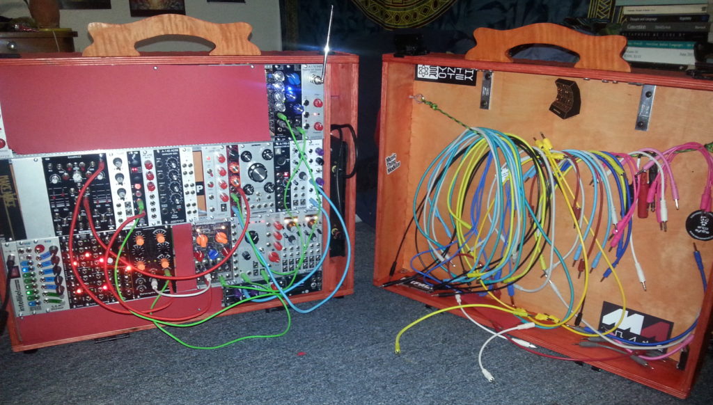
My next step was to throw a little rope across the lid side of the case from which to hang my many colorful cables. The lid was designed so as to be able to fit over the synth while the thing is fully patched. There is a certain sand-painting quality to modular synthesis, in that there are no saved presets in this town. When you pull the plug, the plug pretty much stays pulled.

The Electronics

I’m not an electrical engineer and I am only learning how to read circuits. The first soldering iron I touched was upstairs at AMT. So I’m no expert. I did not build all the modules you see in that case, but I did build half of them. And with the help of resident synth legend Matt (@mhz), I’ve been learning a ton. The plan is to fill the rest of the case with stuff I’ve built myself, which is going well. I wish I had picked up the soldering iron sooner.

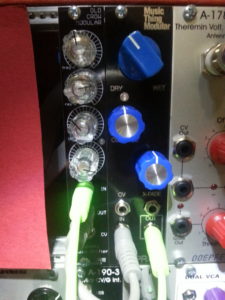
One of my favorite parts is picking the knobs! Here’s a picture of my most recently stuffed board, and a picture of it nicely mounted in the case (next to it is the reverb module that interfaces with the afore-mentioned spring tank). It’s a phase shifter! A clone, in fact, of the popular Small Stone guitar pedal from the 70s.

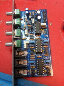
Behold my impeccable taste for knobs!

A really cool thing about the SDIY scene is that a lot of designers release their circuits to the community open-source style.  Which is an awesome learning resource, and makes everything very hackable.

The Future

Going forward, I’m going to continue assembling modules. Over the past few months I went from buying assembled units, to buying kits, to buying PCBs and panels and sourcing my own components. Soon I will get certified for the incredible Laser Cutter (!), and then I will foray into doing my own acrylic panels, which will give me the opportunity to delve deeper into the DIYness.

I spend more time building the synth than I do playing it. SDIY is as much of a hobby as the music/sound design itself. I have decided not to fight this, and am learning how to read schematics, so that I can hack them, and maybe someday come up with my own designs that I can re-release back into the open-source SDIY ecosystem.

So there it is. Thanks for reading. If you want to geek out in greater depth about the nature of modular synthesis or synthesis in general, I’m pretty approachable, and you can slack me @devogenes.

And here’s that other soundbite I promised!

3D CNC Milling a new part for an old lathe – part 2

Continuing the saga of the bed bracket for the Monarch 10EE lathe taper attachement, we left off with a nicely squared up rectangular block of metal, and a Fusion 360 model of the part. The next step is to figure out how to hold the work and machine it to shape. I’ve never done much in the way of 3D milling, so this would be a learning adventure for me.

It’s important to think through the sequence of operations, and how for each operation you are going to 1) hold onto the part, and 2) find the origin for your WCS (work coordinate system). For the first setup it’s usually pretty straight forward as you are starting out with a nice rectangular block with flat sides and square corners, just clamp it in the vise, make the top back left corner the origin, and carve away. But then you have to flip the piece over and do the other side and you’ve just cut off all those flat sides and corners, and the vise might not have anything to grab onto. Having the 3D printed version of the part in hand was definitely helpful in visualizing how to do things and in what order.

For this particular part (see http://a360.co/2iXVoIu and part-1), I could choose to start with milling the top or the bottom. There flat areas on the top, one end, and 2 sides of the part which could be used for references. All the critical dimensions are on the bottom, so my first thought was to mill the bottom first and if I screwed it up I wouldn’t waste time milling the top. But thinking about the work holding once the bottom is milled there isn’t much to grab onto any more for milling the top. Only a very small area of the sides are available for clamping. So, looks like I should do the top first, and hopefully there will be enough of the sides left flat for clamping.

In Fusion 360 created my first setup, Since I had already machined the width of my material to size, picked my stock size to be the “model box”. I made the origin the top back left corner of the rectangular block of stock. It’s good to use one of the back corners for this because the rear jaw of a milling vise is fixed that location should stay the same if you take the part out of the vise, flip it around, etc. That back side of the part, and the face of the fixed jaw of the vise are a solid reference point for all the setups. All of your part will be at negative values of y axis. I like to put my origin on the left size, and then all my x axis positions are in the positive direction. If you do this consistently you will be less likely to make mistakes. If you look at the Mach3 toolpath display and things are going into positive Y or negative X, it will look funny, and you should check what is going on.

Drilling the hole in the top seems like a no brainer, so decided to start with that. Long drill bits are wiggly and can wander when starting. So to get an accurately located hole we can use a spotting drill or center drill. They are short and stiff, and will make the hole wherever you put the point to the metal. At AMT we have a bunch of center drills. The problem with these is that if you make a mistake the tiny little tip can break off in your hole and it’s a bear to get it out again. I had just recently experience this, and decided to buy some spotting drills and see how they work. Turns out they work well, and you would really have to screw up bigtime to break one off in the hole. So first operation is a 0.1″ deep spotting drill hole.

Next we need to drill a clearance hole for a 3/8″ bolt. Looking on the chart a close fit clearance hole for a 3/8″ bolt is size W. Oops. No letter size drills at AMT, or in my tool box (add that to the wish list for next year). So, looking at a drill size chart I see that next size up from W is 25/64″ and I do have one of those, so I will use that. Only turns out that when you put the block in vise, and the drill chuck in the mill there isn’t a lot of vertical space left between the bottom of the chuck and the top of the part. The drill is too long and won’t work. Fortunately, the shank of this particular drill bit is turned down to 3/8″, and it fit securely into the R8 3/8″ collect, which doesn’t take up nearly as much vertical space as the drill chuck. The drill fit in the available height, but just barely.

When drilling a deep hole (more than about 4 times the drill diameter) you need to worry about getting the chips out of the hole. The chips can clog up the flutes of the drill bit, jamming it in the hole and causing the bit to break. So when setting up the CAM for this operation, make sure to set the cycle type to “Deep Drilling”. This will cause the drill to go down a bit, then retract out of the hole to clear the chips, then dive back in, drill a little deeper, and repeat until the correct depth is reached.

Unfortunately, in the process of screwing around with the drills, chuck, collets, etc, I somehow (and I’m not really sure how this happened) screwed up my x-axis location. I fired up the g-code and it started drilling the hole in the wrong place. Yikes! Hit E-stop, but it was already in about 1/4″. So much for my beautiful part. Oh well. It’s right next to the real hole, and a nice washer under the bolt head will just cover it from view. Anyway, I re-homed the machine,  used the edge finder to locate the left and back edge of the block, and successfully drilled the hole in the right place.

Next comes carving out the shape of the top of the part. In the CAM software I picked 3D adaptive clearing since I had heard that this was a good way to do this. It uses the whole length of the side of the end mill and side mills off a constant amount of material on each pass. This supposedly removes a lot of material quickly, and improves the life of your cutter since it uses the entire length and not just the tip. And since I didn’t know how well this was going to work I decided to  leave 0.1″ of extra material to clear out on later finishing passes.

One of the parameters for adaptive clearing is the “engagement” of the cutter. This is how much material it will attempt to side mill off on each pass. I was using a 3/4″ end mill, and so I thought I could take pretty big bites, and picked 0.050″. That’s a pretty small fraction of the 0.75 cutter diameter, so why not. Turns out that a 1.7″ depth of cut with that much engagement and that size cutter take a LOT of horsepower to turn, and it puts a lot of force on the machine. When it started to cut the motor immediately stalled out, and the stepper motors started skipping. Argggh. Back to the CAM program, cut the engagement in half to 0.025″. Re-home the machine, re-find the edges, and try again. Boom! Same thing again. Do it all again, but this time try 0.010″. This time it starts to work, but it makes a terrible noise. On no! E-stop again! The bottom of the end mill is cutting the top of the vise jaw! I forgot to check that. Take my part out of the vise, put a parallel underneath, re-find the edges, and try again.

This time it seems to actually be doing the right thing! It’s taking a bit of material off the back of the part going from left to right, but when it gets to the corner and starts to come around it stalls out again. E-stop again! What’s going on? After some thinking it occurred to me that I had used the bounding box of my part for the stock size in my setup, but when I actually cut the metal, I had not accurately cut it to length. I had left a little extra to mill off later. Well the CAM software doesn’t know that metal is there and happily drives the cutter into what it thinks is 0.010″ of metal, but what was really there was 0.1″ of metal. Back to the CAM software and add the extra metal to my stock size, re-home, re-edge find, and try it one more time.

This time it’s working! The big end mill is actually carving out the shape of the top of my part! Time for a celebratory beer? No wait. Taking off only 0.010″ of material on each pass it is going to take about 90 minutes to finish. And long needles of aluminum are flying all over, and so I watch, vacuuming up the mess as it goes until it is finished.

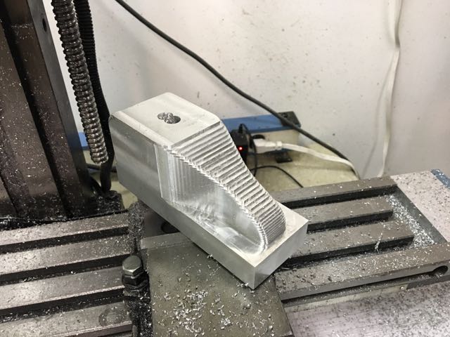
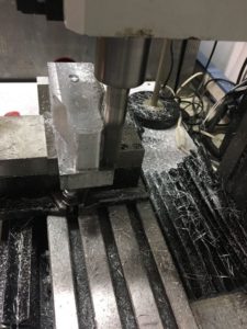
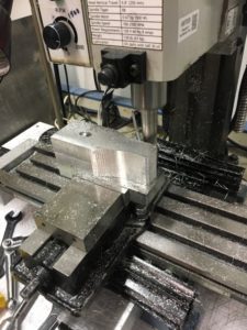
Remember that 0.1″ of material I left in the setup of the adaptive clearing pass? Well now it’s time to take that off. I look at my options in the 3D milling CAM operations and see that “Contour” is a finishing strategy that is good for steep sided things like my shape, so I give that a try.

Surprisingly this works with no problems. How can that be? Something that does what I expect the first time? I decide to quit while I am winning and save the rest for another day. Here’s a picture of where I stopped.

Next steps are to go over the curvy areas of the top with a 3/4″ bull nose end mill, then flip it over, and mill the bottom. That will have to wait until I get back to it a week from now. Stay tuned for part 3.


3D CNC Milling a new part for an old lathe – part 1

As some of you know, besides my Tool Steward duties in the ATM Metal Shop, I also have a similar role with the Eastbay Astronomical Society. I help take care of their metal shop located up at Chabot Space & Science Center. One of the key tools up there is a 1964 Monarch 10EE Toolroom Lathe, which was donated by the USDA a few years back.

This is an amazingly accurate and powerful lathe that has all kinds of useful features and functions, one of which is a taper attachment. A taper attachment is an accessory for a lathe that, as the name implies allows one to cut very accurate tapered parts. For example, the tailstock of AMT’s Jet 9×20 lathe has an #2 Morse taper socket into which can be plugged all sorts of centers, drill chucks, drill bits, etc. Unfortunately, one pice of the taper attachment for the Monarch lathe was missing when we got it, and the that has prevented using it. My project is to create a replacement for this part, which is a bracket that securely attaches the sliding part of the taper attachment to the bed of the lathe.

A bit of research on the web found this drawing of what the original looked like

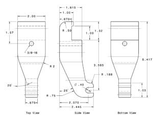
It looks like kind of a complicated part to make, and the material would be expensive, so I decided to try a 3D printed prototype to make sure it will fit. First I created a model in Fusion 360 based on the measurements in the drawing. I haven’t tried this before, but I think you can view the model at http://a360.co/2iXVoIu.

Then I 3D printed it on AMT’s Makerbot. Here’s what I got

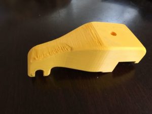
I then took this plastic version of the bracket up to the lathe to try it on for size. Good thing I did because it didn’t fit. The arm of the bracket was too long for my lathe and I would have wasted a big chunk of aluminum of I had just dived right in. Perhaps Monarch made multiple versions of the lathe over the years and the plan I found was for a different one? Anyway, I corrected the model, printed out another version and this time it fit perfectly. It’s time to commit to metal!

Drove down to Gorilla Metals in Hayward and bought enough 2″ x 2.5″ Al to make 2 since I figured I would screw up somehow. Also found a bunch of nice materials in their cutoff pile, paid for it all, put the scrap in my car, and drove home, leaving the actual bar I had driven all the way there for on the counter. Next day drove back, and picked it up with some mild ribbing from the friendly folks at the counter.

First thing to do was to cut a 5.5″ piece of the 12″ bar I had brought home. Turns out the 10 TPI blade for the horizontal bandsaw is terribly dull, and after 5 minutes had barely made a dent. Time to order some new blades for that thing. So then moved to the vertical bandsaw to see if that was better. Definitely! Was done in about 5 minutes.

Just like wood from the lumber yard, extruded aluminum bars are not flat and square when you get them, so clamped my raw stock into the milling machine vise, loaded up a fly cutter, and proceeded to flatten and true up all 6 faces making a close to a perfect rectangular block as I  could. The fly cutter left some marks, but not too bad, but it may be time to take a closer look at the tram of our mill. the column seems tilted ever so slightly towards the front. A project for the new year.

Next post will discuss a bit about CAM and workholding for turning this blank into the actual part.

Darth Vader Concrete Planter

This project began when I found a halloween basket of Darth Vader on sale after Halloween – $2.50.  I’ve been looking for project to learn/practice/experiment with silicone molds, so I chopped up the mask to make a two part mold.

original mask

I wanted the cavity to remain hollow so it could serve as a planter, so I built a box out of foam core and hot glue and placed the mask face up.  I placed one edge of the foam core right up against the top of the mask to block out the cavity – lots of hot glue on the underside to keep the silicone out.

Despite having watched a variety of videos on youtube, i tried a different process to make the two piece mold in two separate boxes.  Big mistake!

darth vader mask mold – smooth on Oomoo 30

The mold had great detail, but the two pieces didnt match up.  I tried to patch and fill, and it probably can be done, but i was in a rush to get on a plane and try to cast one of these for x-mas.  The result was some unevenness in the bottom, and spalling out of the sides which could be cleaned up better.

darth vader concrete planter


I also didn’t pour it up high enough to the top, in part because my solution for the cavity was a failure due to lack of proper materials and time.  The details came out pretty well despite taking it out too soon.

I also experimented with some concrete coloring agent and made this death star paper weight.  I prepared too much material so I poured a bit of Darth’s mask to see how the color would be.

death star paper weight
darth vader concrete with color

Its hard to see the color in the death star due to the lighting, but the mask shows the much darker charcoal color than the planter.   I think with some added colorant, it would be a nice deep black.


The mold required ALOT of material.  The stock we had at AMT was expired and hard when I opened the bottle, and it ended up taking 3.5 bottles, so essentially $100.

It was like taking a class for $100, which I’d have paid anyway, and I’ve got a half decent mold that can be used.  Im not sure how I would try making it again so that the molds could better align due to the cavity I want to keep.  If it were a solid head, you could build the box and just pour the material over the entire bust, and maybe that will still work if I figure out a way to cover the cavity.

Sorry for the sideways pics, I couldn’t rotate them for some reason.

3D printing tool board

It’s a simple thing, but one I’ve been meaning to do for a while.  When your tools have a visible home, you can instantly see when one needs to be put away.

These are the tools I routinely use, but this is meant to be a living thing, so if you think an additional tool should go there, add a screw and a label.

3dp-tools-closeup

Tool Board

I wanted to hang my most-used tools on the wall just over my workbench/desk.

Pegboard might seem like the obvious choice, but I’ve never really liked it: The hole grid dictates positions that never seem quite right, and there’s always some tool that just doesn’t work with the standard pegboard hardware. Also, that hardware can be surprisingly expensive once you get everything you need (and the extra parts you think you’ll need but never use).

At the other end of the spectrum live craftsmen who create a custom holder for each tool, complete with six coats of varnish and an elaborate french-cleat mount system. I don’t live there. Not even in the same town.

Instead, I just wanted a simple plywood board to host any random screws, nails, cup hooks, or screw eyes that do the job. Whenever the mood strikes me, I want to be able to just hang something up, without having to go find some weird hardware or make a custom fixture. I don’t want to think about it; I just want it done.

Plywood board used to make tool board
Plywood used to construct tool board

Today, in the intro to woodshop class, I spotted a 2’x4’x3/8″ plywood sheet just perfect for the job. No blue tag, so it became mine. This was my first woodworking project at AMT. I finished it in about 45 minutes this afternoon.

I  wanted to stiffen it and separate it from the wall in case I drive one of those cup hooks a bit too deep. I bought two 1×2 strips at the home center and made a simple frame. It’s glued and screwed to the tool board with wood glue and #8 wood screws. I have no photos of the exciting build process, since Hugh only suggested the contest after I had it done. (He gets the laptop if I win, btw. I really don’t need two.)

Strips of wood attached to plywood
Bracing added to back of board

The only power tools I used were the chop saw and two drills: One to drill pilot holes and the other to drive screws. Sure speeds things up. This is the kind of project that could be done at home, but it’s just so much nicer to work on a proper bench with enough clamps to hand, the extra drill, etc.

Back at my workshop/office, I discovered I no longer have a stud finder. Must’ve given that away in my
Tools hanging on board
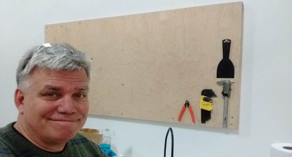
most recent purge of extraneous stuff. I borrowed a magnet from the fridge and hung it from a piece of string… which actually seemed to work better than the old stud finder. Two 3″ #8 screws hold my
board up. It seems very solid, but as I add things it might get heavy, so I’m thinking about adding a couple more. I drilled clearance holes in my board for the mounting screws, so the threads only bite into the wall studs. This way the screws can cinch the board up snug to the wall.

Man with tool board
Mat and his tool board

As you can see, I only have a few things hung so far, all with 3/4″ #6 wood screws. It took me about two minutes to do that much; I just drove the screws straight into the plywood without even bothering to drill pilot holes. The caliper is a good example of a tool that would not be convenient to hang on a pegboard, yet two screws do the job nicely on my tool board.

I still have a big mess to clean up, but I already like my tool board better than any I’ve used before. It feels nice to undercomplicate something for a change.


AMT Coasters

As Makers we see the potential in everything which leads to hoarding. I will admit to hoarding stuff far more than I should and one of those things I kept around longer than I need to was hardwood flooring samples. Such beautiful wood! We can make things out of this beautiful wood! And finally, years later, we did.

3 wooden coasters
3 Coasters

All these coasters where made on the big CNC router out of flooring sample boards. You can get these for free or really cheap off the interwebs, the downside is you are constantly emailed and called by flooring salesman in followup. My first attempt was in doing the full AMT logo in a fine cut using a 0.9mm bit. Having such a large machine use such a small bit was funny in that Laurel and Hardy kind of way you expect. I found that I was breaking bits constantly, even when changing around the feeds and speeds. Eventually I gave up and switched over to using just a 1/8″ down cut spiral bit for engraving the top with the logo and for cutting out the coaster when done. These are less fine detailed but do have the advantage of not destroying a ten pack of bits. I used spray adhesive on the back to glue down a shelf liner backing.

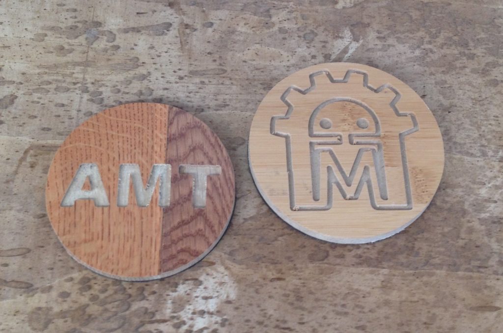
That works… sorta and for a short time. Need to come up with a better solution for putting a non-stick backing on these guys. Overall I’m pleased that we still have most of them around AMT, I thought they would be gone in a few weeks but here we are months later and you can always find a coaster  upstairs when you need one.
Now what to do with the box of flooring samples I still have….

dragon egg made of thumbtacks

Dragon Scale Egg

Materials Needed:

  • Styrofoam egg
  • Approx 550 thumbtacks
  • Cardboard to hold thumbtacks
  • Choice of nail polish or spraypaint
  • Clear coat
  • Glue
thumbtacks on cardboard
lots of thumbtacks
dragon egg made of thumbtacks
finished dragon scale egg made of thumbtacks and a styrofoam egg

The most tedious part of this project is sticking approx.. 550 thumbtacks onto a piece of cardboard. This step, however, makes the painting of the thumbtacks much easier, especially if you plan to use spraypaint.

Painting the thumbtacks

Paint each thumbtack – two coats may be needed if you want to eliminate any marks on the top side of the thumbtack. A much quicker method is to use spraypaint. You will want to use spray paint that is suitable for automobiles. If you want some of the shininess of the thumbtacks to come through the paint, you can start by spraying a clear adhesion promotor first. This can be found at any car parts store, along with a wide selection of spray paint suitable for metal.

Once the thumbtacks are dry, take one and place it in the top center of the styrafoam egg. Put the next thumbtack beneath the first, with it barely overlapping. Now follow a pattern like a swirl, around the egg, with each thumbtack barely overlapping the one above it and the one right next to it. By overlapping the thumbtacks, you lock them in place without the need for any glue.

When you get to the last tack at the bottom of the egg, place some glue on the bottom of the head before sticking it in. The glue is needed because there are no more tacks to lock it into place.

Now spray the egg with several coats of clear coat, which will give the egg a glossy sheen as well as help bind the thumbtacks to each other. I have also heard that some folks use mod podge as a final clear coat, which would also cause the tacks to better adhere to each other.

South Pointing Chariot

A South Pointing Chariot is a vehicle carrying an indicator that always points South. As usual, there’s a good article on Wikipedia.

While the device was mentioned in a number of ancient Chinese texts, no design or construction details have survived.  My model (like many others) assumes that a differential gear train was employed.

It’s been a fun project, but it’s a bit too difficult to assemble, and the wheels need work.  watch this space for an updated version, including full CAD source files.

-Matt

Skull

Mr. Skull

I have been wanting to put *something* in the eyes of a cheap plastic skull for a few years now. As makers we see the potential in everything and every year at Halloween I see these plastic skulls that scream out for hacking. This last Halloween I noticed that Target was selling extra large skulls and thought, hmmm, probably can fit a 32mm square LED matrix in that eye socket. A quick trip over to the office supplies area, grab a ruler, come back and with a few measurements decide to give it a shot.

Skull
Captions are nice

This was also for the AMT booth at East Bay Mini Maker Faire to have something interactive that people could play with via their phones. For that I needed a wifi server and for that it was time to try my hand at programming a ESP8266 board. I had picked up a NodeMCU module that is a good breakout for the ESP8266 and started to figure out how to use it. Right about then I found you could program it via the Arudino IDE and someone had posted some example web server code where people enter text and you can process it and do stuff.

Armed with this and a few MAX7219 LED matrix modules I jumped in. There was much flailing about programming wise. As a programmer I’m a good salesman. Finally after getting the code to sorta work I needed to cut open square windows for the LED matrixes. Matrixi?

I was lucky enough to find a tinted piece of 1/4″ acrylic in the scrap bin at AMT that would work. I figured out the spacing of where each matrix should go and laser cut out the holes to hold the LEDs in place. After that it was time for open up Mr. Skull. I cut an opening in the back of his head that would allow me to just put a hand inside. Putting in the acrylic with the LED modules attached, I then took a hot glue gun and without being able to see inside, started to squirt hot glue everywhere inside the head of Mr Skull in the hope that some of the glue would hold the acrylic with the LEDs in place. It just did.

Finding a music stand to put up Mr Skull was a nice surprise. Ever since then he’s been guarding the upstairs and waiting to see what people put in the text box of his website.

I hope to put say a Twitter feed and/or word clock into him at some point. Always upgrades to be done in projects.