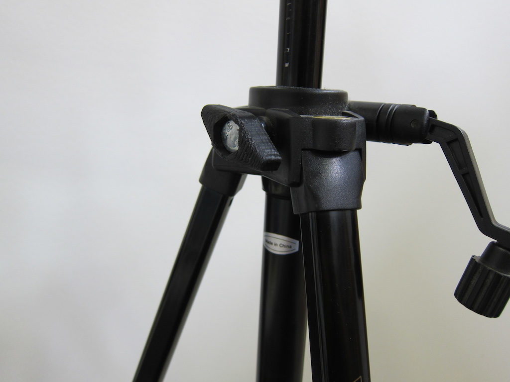
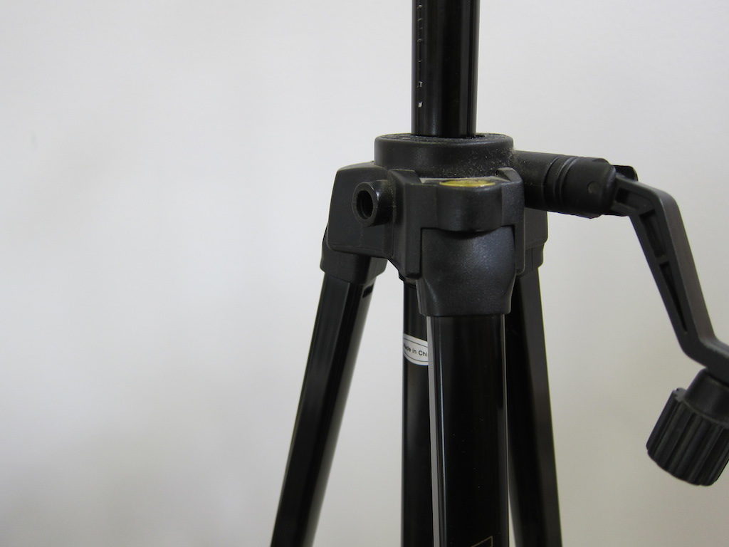
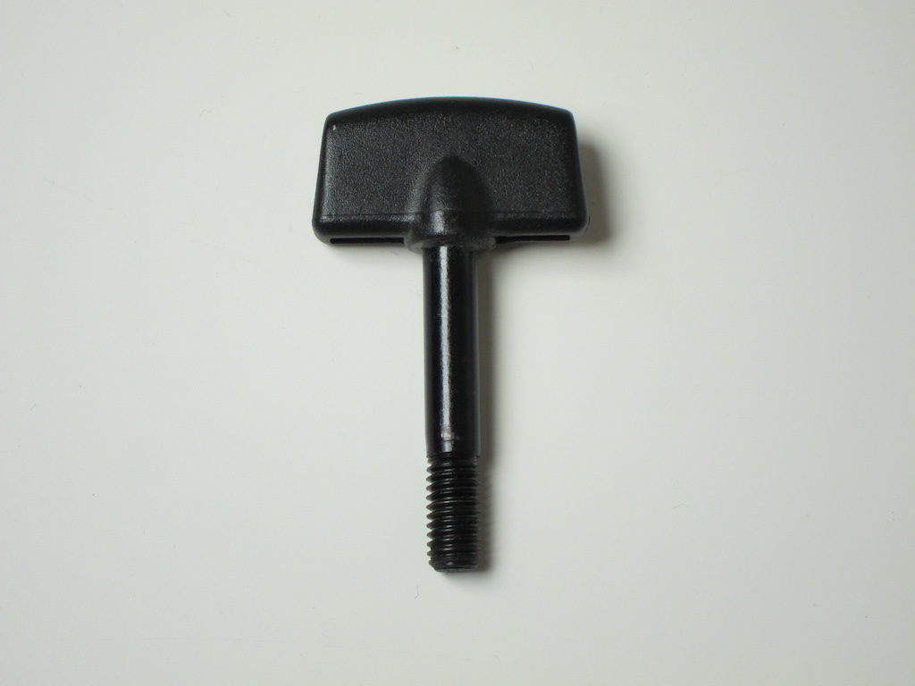
I dug my camera tripod out of storage the other day only to discover that one of the knobs has escaped. A great chance to use a 3D printer for something more than a ‘cereal box toy,’ as Hugh puts it.
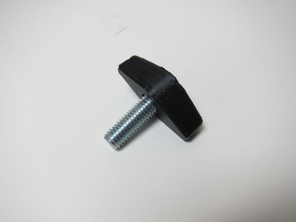
 I rooted around in my Box O’ Loose Screws and found a bolt that fits. Unfortunately it’s a cap-screw type, and I was afraid my knob would slip and wear loose over time. So, I went to the hardware store and found an equivalent with a hex-head. I thought I might just be able to find a star-knob while I was there, but this turned out to be a metric size (M8). The head of my new bolt is just under 13mm across the flats, so I’ll start my design around that.
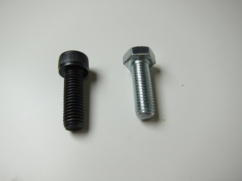
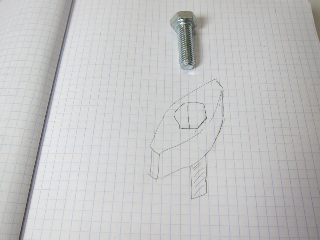
I’m thinking I’ll make a plastic knob that a conventional bolt fits into. Since I’m making my own, I can also try to duplicate the style of the existing knobs on the tripod.
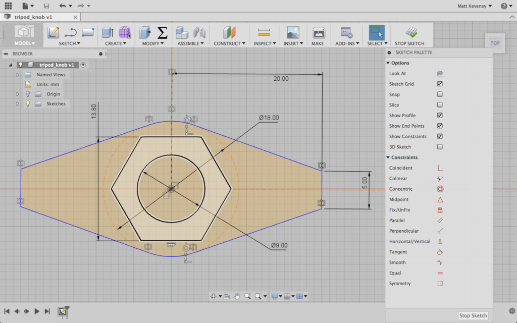
First I create a sketch on the XZ plane with the hex head centered. I create a hole for the threaded part to fit through; a construction circle to which I can align the flat sides of the ‘wings,’ and then the wings themselves. This sketch describes three distinct profiles: the innermost hole; the hex hole, and the wings. Fusion 360 highlights these profiles as you hover with the mouse; in the following screenshot, the hex profile is highlighted.
I extrude the outermost profile upward to create the wings.
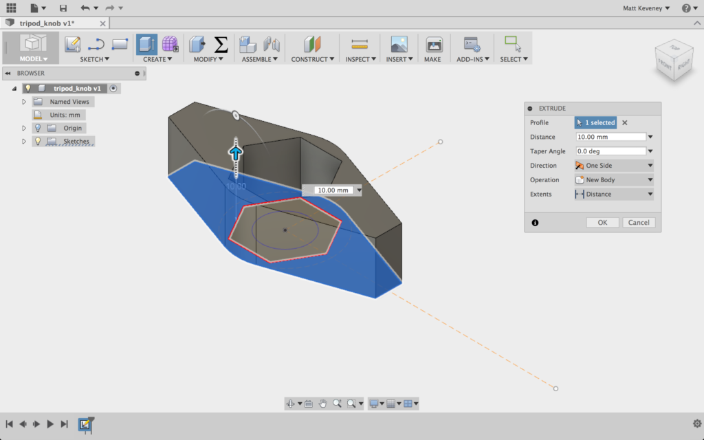
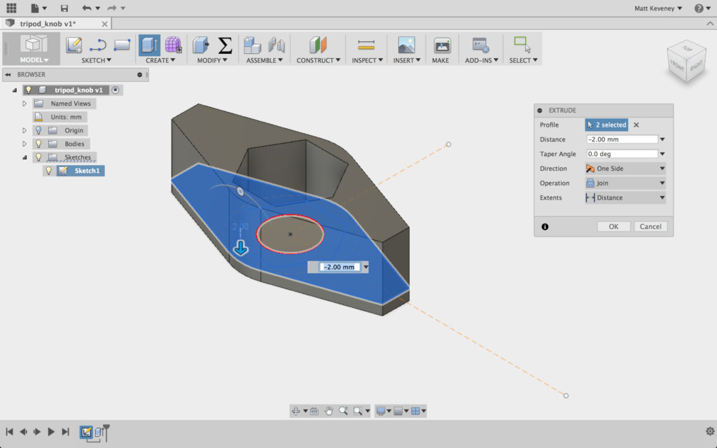
And I extrude the outermost and hex profiles downward slightly to create the flat part that traps the nut. This also extends the wings downward.
I could stop right here and have a functional part. If I was in a hurry that’s what I’d do, but I’ll keep going just so I can illustrate a few more Fusion 360 tricks.
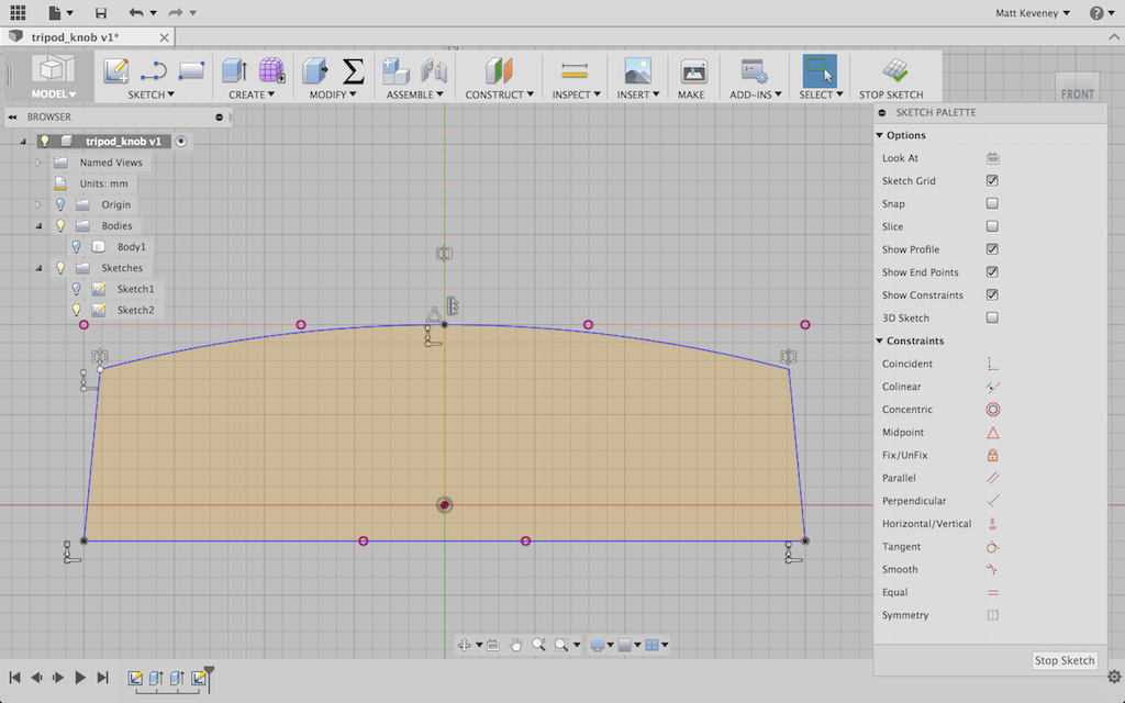
On my tripod’s other wing-knobs the side profile is slightly rounded on top, and has ends that slope inward slightly. Retaining this design detail might make my new part look more like it belongs.
I’ll create another sketch on XY plane for this. Note that this sketch plane bisects the current body; that’s OK. I first project the intersection of the top and bottom face of the body into my new sketch, then hide the body. Then I select the projected lines (the purple ones) and click X to convert them to construction lines. Now I can draw the rest of the sketch, using the construction lines to guide my work.
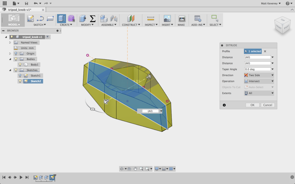
Then I turn the body back on and extrude this profile, using a symmetric direction and the intersect operation.
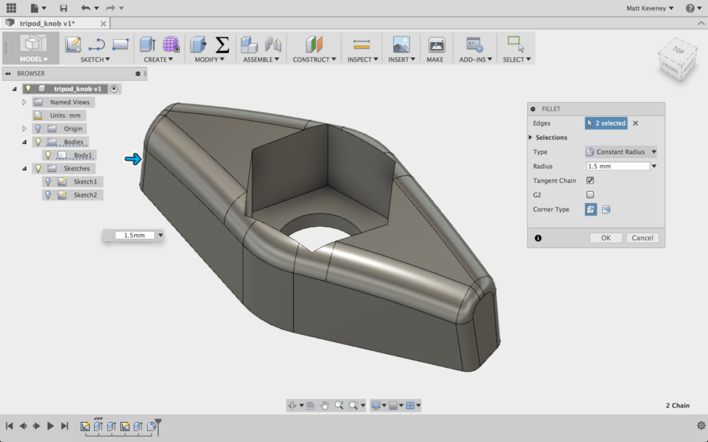
Now, I use the fillet tool to round the edges a bit. I’m a big fan of the fillet tool for parts that get handled frequently; it really makes a big difference in the feel of the part.

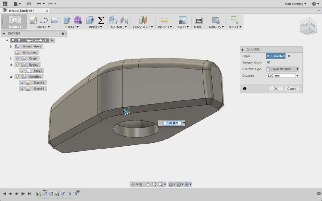
I’m planning on printing this oriented with the hex hole upward. If I fillet the bottom edges of the part, I may get sloppy results, since the start of the fillet curve is over our overhang limit. I’ll simply use the chamfer tool instead.
Let’s print it out! I generally use two perimeters and four layers top and bottom. In this case I’ll use 25% fill. I really only use three fill settings: 15%, 25%, and 40%. I don’t think the percentages reflect the density of the part; 40% is nearly solid.
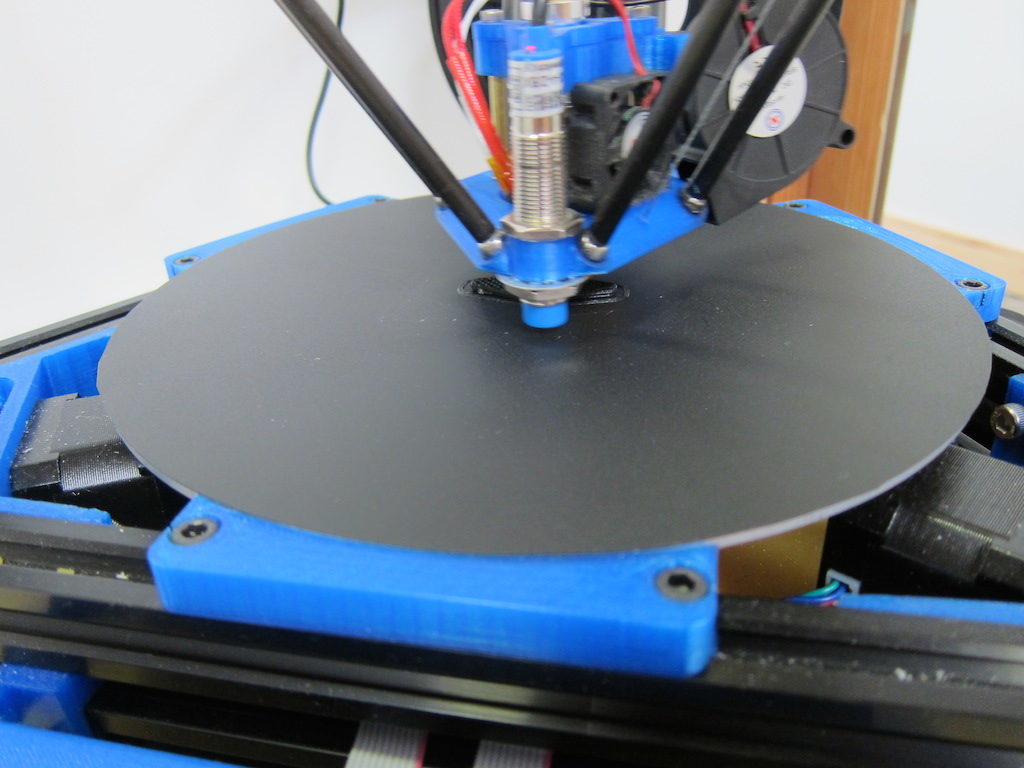
It works!