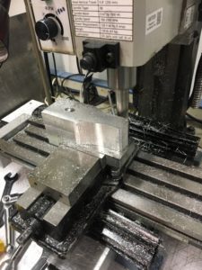
Continuing the saga of the bed bracket for the Monarch 10EE lathe taper attachement, we left off with a nicely squared up rectangular block of metal, and a Fusion 360 model of the part. The next step is to figure out how to hold the work and machine it to shape. I’ve never done much in the way of 3D milling, so this would be a learning adventure for me.
It’s important to think through the sequence of operations, and how for each operation you are going to 1) hold onto the part, and 2) find the origin for your WCS (work coordinate system). For the first setup it’s usually pretty straight forward as you are starting out with a nice rectangular block with flat sides and square corners, just clamp it in the vise, make the top back left corner the origin, and carve away. But then you have to flip the piece over and do the other side and you’ve just cut off all those flat sides and corners, and the vise might not have anything to grab onto. Having the 3D printed version of the part in hand was definitely helpful in visualizing how to do things and in what order.
For this particular part (see http://a360.co/2iXVoIu and part-1), I could choose to start with milling the top or the bottom. There flat areas on the top, one end, and 2 sides of the part which could be used for references. All the critical dimensions are on the bottom, so my first thought was to mill the bottom first and if I screwed it up I wouldn’t waste time milling the top. But thinking about the work holding once the bottom is milled there isn’t much to grab onto any more for milling the top. Only a very small area of the sides are available for clamping. So, looks like I should do the top first, and hopefully there will be enough of the sides left flat for clamping.
In Fusion 360 created my first setup, Since I had already machined the width of my material to size, picked my stock size to be the “model box”. I made the origin the top back left corner of the rectangular block of stock. It’s good to use one of the back corners for this because the rear jaw of a milling vise is fixed that location should stay the same if you take the part out of the vise, flip it around, etc. That back side of the part, and the face of the fixed jaw of the vise are a solid reference point for all the setups. All of your part will be at negative values of y axis. I like to put my origin on the left size, and then all my x axis positions are in the positive direction. If you do this consistently you will be less likely to make mistakes. If you look at the Mach3 toolpath display and things are going into positive Y or negative X, it will look funny, and you should check what is going on.
Drilling the hole in the top seems like a no brainer, so decided to start with that. Long drill bits are wiggly and can wander when starting. So to get an accurately located hole we can use a spotting drill or center drill. They are short and stiff, and will make the hole wherever you put the point to the metal. At AMT we have a bunch of center drills. The problem with these is that if you make a mistake the tiny little tip can break off in your hole and it’s a bear to get it out again. I had just recently experience this, and decided to buy some spotting drills and see how they work. Turns out they work well, and you would really have to screw up bigtime to break one off in the hole. So first operation is a 0.1″ deep spotting drill hole.
Next we need to drill a clearance hole for a 3/8″ bolt. Looking on the chart a close fit clearance hole for a 3/8″ bolt is size W. Oops. No letter size drills at AMT, or in my tool box (add that to the wish list for next year). So, looking at a drill size chart I see that next size up from W is 25/64″ and I do have one of those, so I will use that. Only turns out that when you put the block in vise, and the drill chuck in the mill there isn’t a lot of vertical space left between the bottom of the chuck and the top of the part. The drill is too long and won’t work. Fortunately, the shank of this particular drill bit is turned down to 3/8″, and it fit securely into the R8 3/8″ collect, which doesn’t take up nearly as much vertical space as the drill chuck. The drill fit in the available height, but just barely.
When drilling a deep hole (more than about 4 times the drill diameter) you need to worry about getting the chips out of the hole. The chips can clog up the flutes of the drill bit, jamming it in the hole and causing the bit to break. So when setting up the CAM for this operation, make sure to set the cycle type to “Deep Drilling”. This will cause the drill to go down a bit, then retract out of the hole to clear the chips, then dive back in, drill a little deeper, and repeat until the correct depth is reached.
Unfortunately, in the process of screwing around with the drills, chuck, collets, etc, I somehow (and I’m not really sure how this happened) screwed up my x-axis location. I fired up the g-code and it started drilling the hole in the wrong place. Yikes! Hit E-stop, but it was already in about 1/4″. So much for my beautiful part. Oh well. It’s right next to the real hole, and a nice washer under the bolt head will just cover it from view. Anyway, I re-homed the machine, used the edge finder to locate the left and back edge of the block, and successfully drilled the hole in the right place.
Next comes carving out the shape of the top of the part. In the CAM software I picked 3D adaptive clearing since I had heard that this was a good way to do this. It uses the whole length of the side of the end mill and side mills off a constant amount of material on each pass. This supposedly removes a lot of material quickly, and improves the life of your cutter since it uses the entire length and not just the tip. And since I didn’t know how well this was going to work I decided to leave 0.1″ of extra material to clear out on later finishing passes.
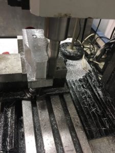
One of the parameters for adaptive clearing is the “engagement” of the cutter. This is how much material it will attempt to side mill off on each pass. I was using a 3/4″ end mill, and so I thought I could take pretty big bites, and picked 0.050″. That’s a pretty small fraction of the 0.75 cutter diameter, so why not. Turns out that a 1.7″ depth of cut with that much engagement and that size cutter take a LOT of horsepower to turn, and it puts a lot of force on the machine. When it started to cut the motor immediately stalled out, and the stepper motors started skipping. Argggh. Back to the CAM program, cut the engagement in half to 0.025″. Re-home the machine, re-find the edges, and try again. Boom! Same thing again. Do it all again, but this time try 0.010″. This time it starts to work, but it makes a terrible noise. On no! E-stop again! The bottom of the end mill is cutting the top of the vise jaw! I forgot to check that. Take my part out of the vise, put a parallel underneath, re-find the edges, and try again.
This time it seems to actually be doing the right thing! It’s taking a bit of material off the back of the part going from left to right, but when it gets to the corner and starts to come around it stalls out again. E-stop again! What’s going on? After some thinking it occurred to me that I had used the bounding box of my part for the stock size in my setup, but when I actually cut the metal, I had not accurately cut it to length. I had left a little extra to mill off later. Well the CAM software doesn’t know that metal is there and happily drives the cutter into what it thinks is 0.010″ of metal, but what was really there was 0.1″ of metal. Back to the CAM software and add the extra metal to my stock size, re-home, re-edge find, and try it one more time.
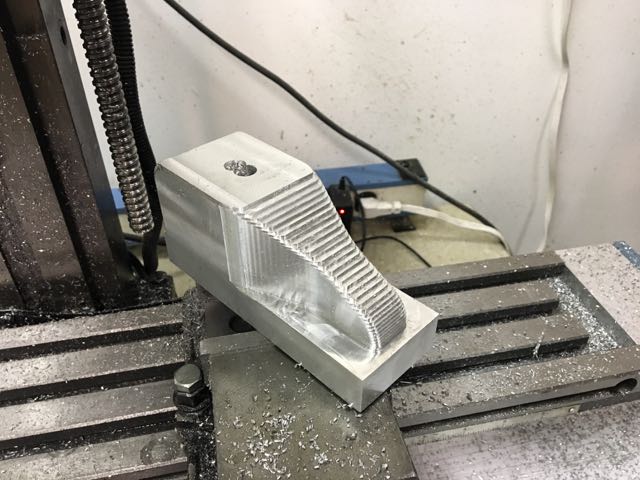
This time it’s working! The big end mill is actually carving out the shape of the top of my part! Time for a celebratory beer? No wait. Taking off only 0.010″ of material on each pass it is going to take about 90 minutes to finish. And long needles of aluminum are flying all over, and so I watch, vacuuming up the mess as it goes until it is finished.
 Remember that 0.1″ of material I left in the setup of the adaptive clearing pass? Well now it’s time to take that off. I look at my options in the 3D milling CAM operations and see that “Contour” is a finishing strategy that is good for steep sided things like my shape, so I give that a try.
Surprisingly this works with no problems. How can that be? Something that does what I expect the first time? I decide to quit while I am winning and save the rest for another day. Here’s a picture of where I stopped.

Next steps are to go over the curvy areas of the top with a 3/4″ bull nose end mill, then flip it over, and mill the bottom. That will have to wait until I get back to it a week from now. Stay tuned for part 3.