Author: Matt Keveney

3D printing steward, CAD geek, software engineer, and technological history buff.

3D print meeting wrap-up, July 26, 2016

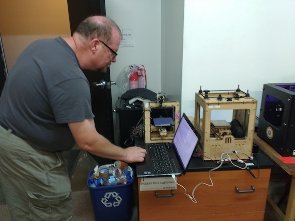
Wow, just one attendee at tonight’s 3D print meeting. Do I have bad breath? Maybe changing the day loused a few folks up? Or maybe we just can’t compete with the Democratic convention.

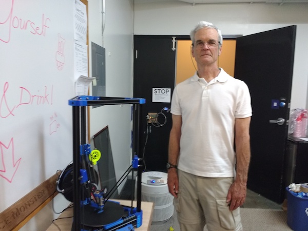
Newcomer Bob came by and introduced himself. We had a nice chat. Bob has his own shop, including a few 3D printers. He’s an experienced designer, and was just wondering how he might contribute. So, if you need some design help, maybe he’s your guy! Let me know and I’ll put you in touch.

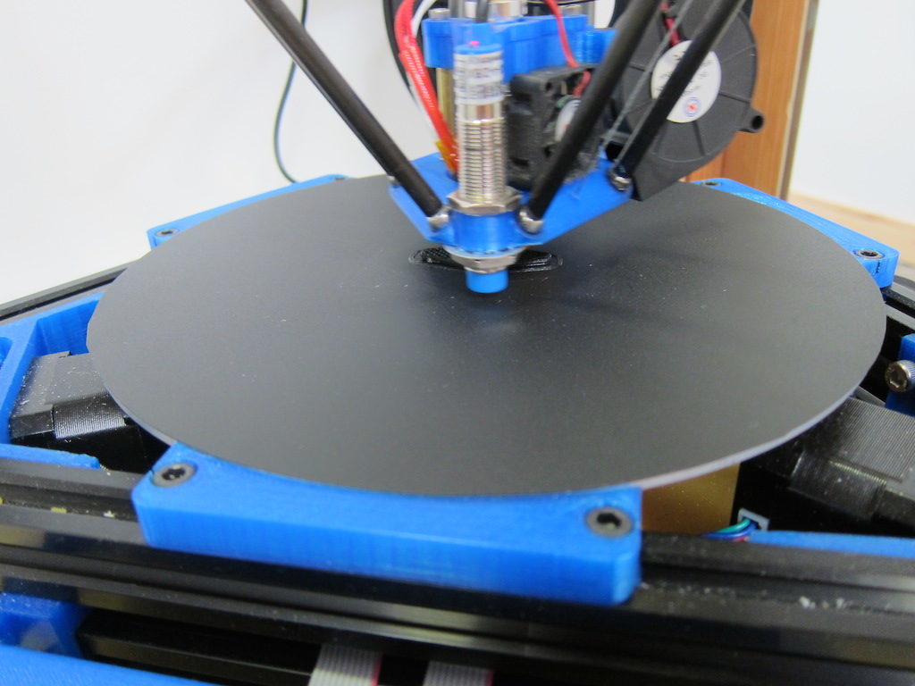
But, just to have a few pictures to show off, I thought I’d post these.  I’ve been playing around with ideas for a 3D printer design.

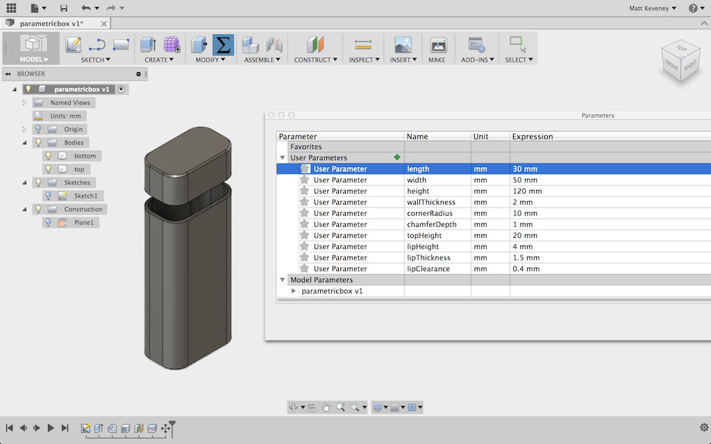
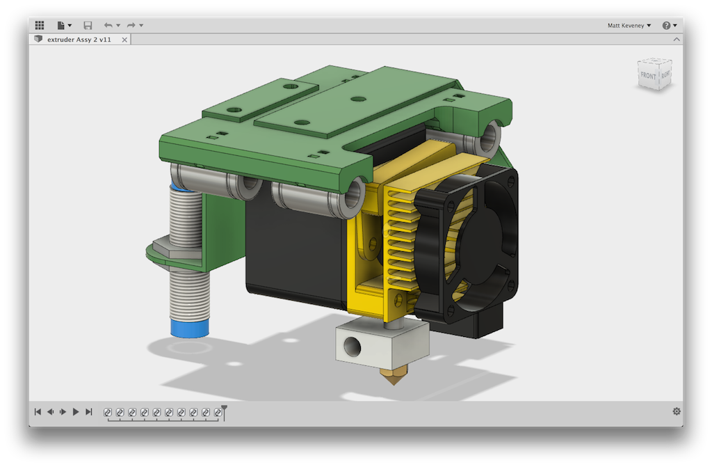
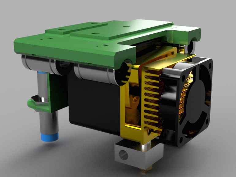
After last night’s Fusion 360 class, I decided to try Fusion’s rendering feature. Here’s a screenshot of the normal modeling environment to compare with the rendered image above. I have not experimented with all the available settings, so I’m sure there’s more to be found here, but I’m impressed with how realistic it looks.  That heat sink is supposed to be anodized aluminum; looks spot-on to me!

3dp-extruder-modelspace

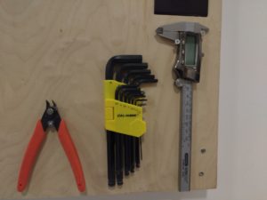
3D printing tool board

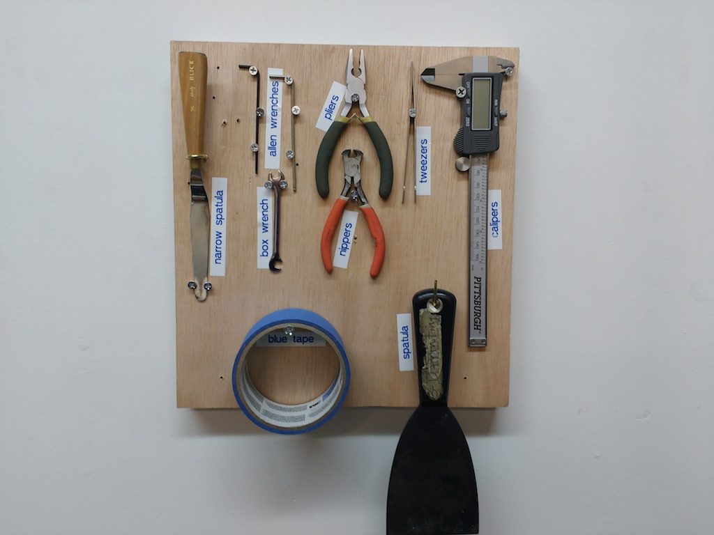
It’s a simple thing, but one I’ve been meaning to do for a while.  When your tools have a visible home, you can instantly see when one needs to be put away.

These are the tools I routinely use, but this is meant to be a living thing, so if you think an additional tool should go there, add a screw and a label.

3dp-tools-closeup

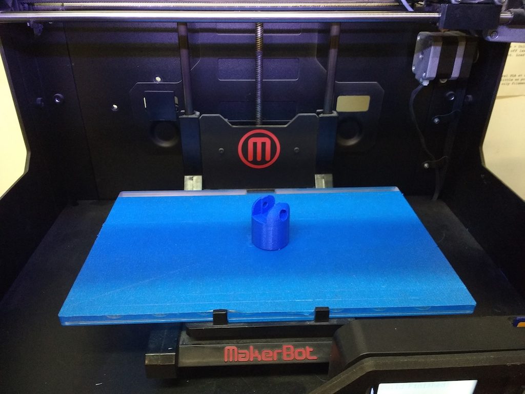
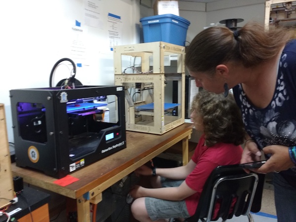
The Replicator 2 is back on-line

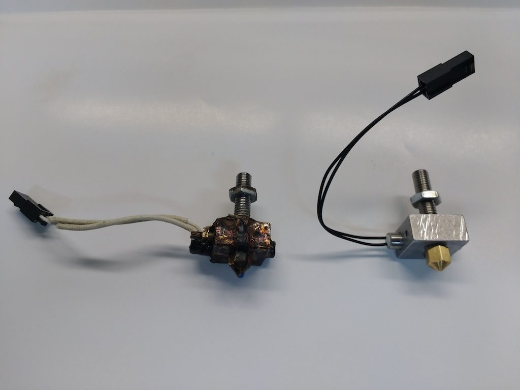
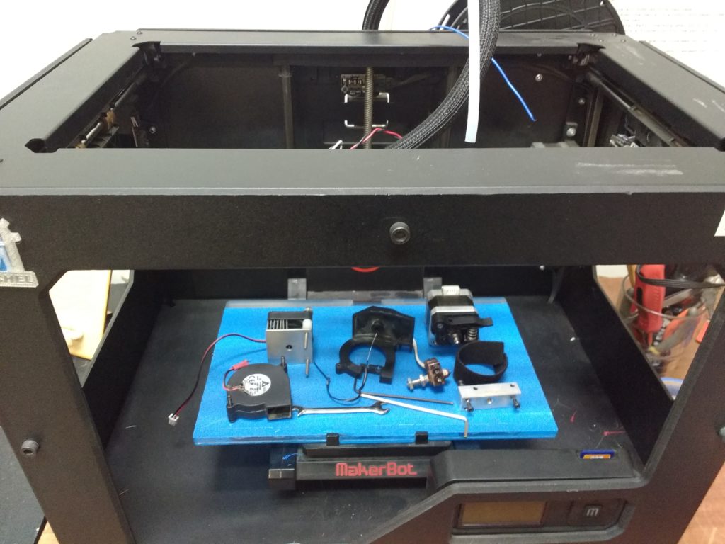
The thermocouple was the only part that actually needed replacing, but while I had everything apart, I also replaced the heater block, nozzle, transfer tube, heating element and thermal insulation. The old one was gunked-up with heaven knows how many years’ worth of melted-on crud.

3dp-rep2-old-and-new-hotends

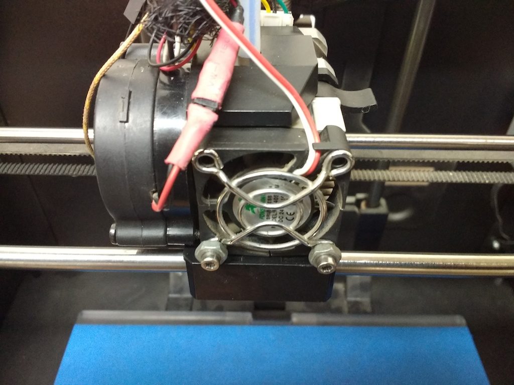
Another issue was the front fan. The Replicator 2 has two fans; one on the front and one on the side. The side fan blows cooling air onto the workpiece. It’s the one controlled by the setting in the Makerbot slicer. Typically it’s off for the first layer and on for the rest. (Turn it off for the whole job when printing with PET). Please use the slicer setting and do not unplug the fan to disable it!

3dp-rep2-sidefan

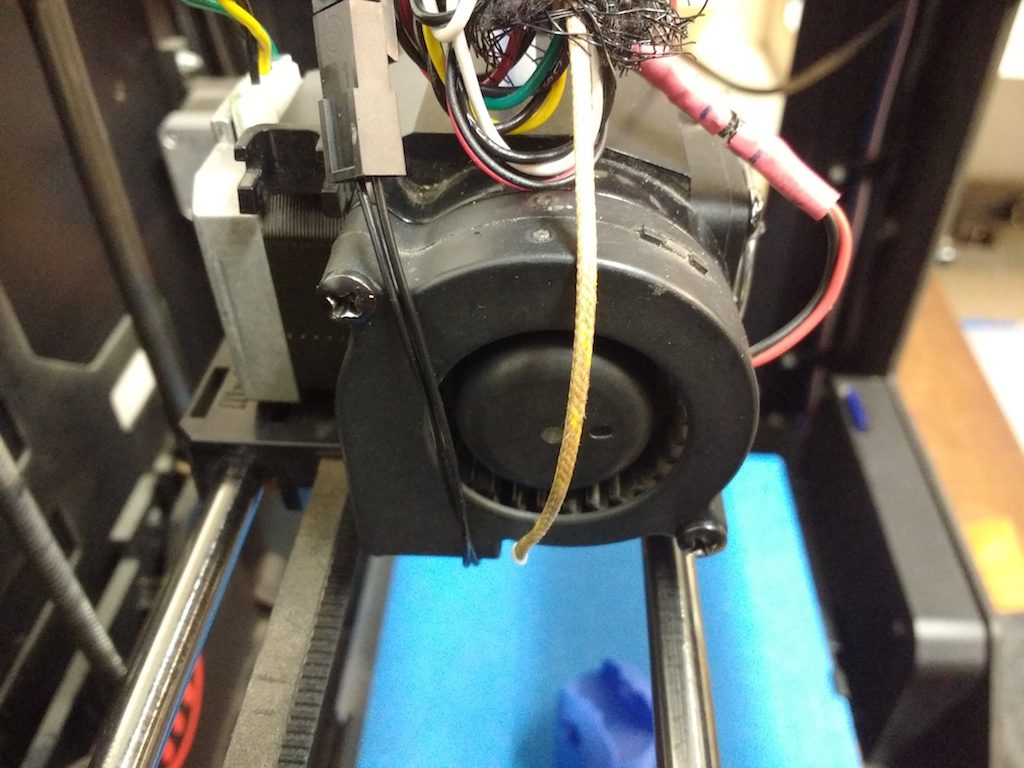
The one on the front should be on whenever the heating element is on. This one sucks air through the heat sink, disposing of the excess heat that travels upward from the heating element. It must be in working order or heat will build up and melt the rest of the extruder assembly! Make sure this fan comes on when you start your print job or change filament… anytime the nozzle gets hot. If the fan does not come on, please cancel your job immediately and contact me!

It turned out this fan had a shorted wire. I found a pigtail up in electronics with the right kind of connector and soldered it to the fan. The sharp-eyed will notice that the color coding does not match the wire it plugs into; rest assured it’s correct. There’s a broken blade on the fan, so I have a replacement on the way, but meanwhile we should be OK.

3dp-rep2-frontfan

One more note: A few weeks back, someone mentioned on Slack that one of the ‘home’ switches was not working, causing a grinding sound at the start of the print job. I got the same sound to happen the other day (before the breakdown), when one of the loose wires on the extruder snagged on the left-front corner of the frame, right after the warm-up sequence. It sounds just like a failure of a homing switch. It could be that this is what broke the fan, but I can’t be sure.

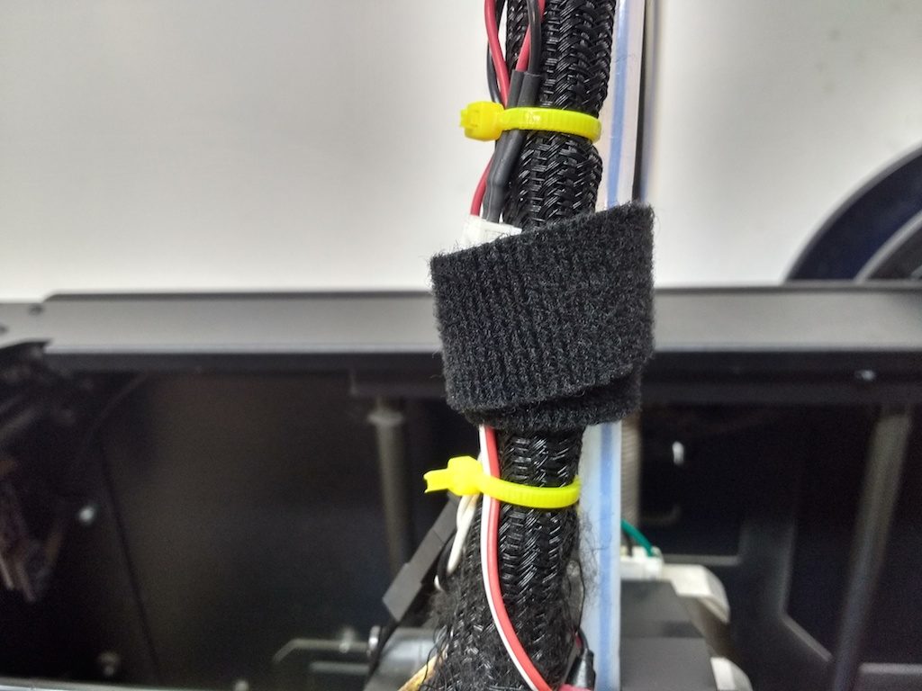
Anyway, I’ve added some wire ties to keep the wire bundle under control. You should not have to unhook any of the wires on the extruder under normal use. If you have to disassemble the extruder to clear a jam, snip the wire ties if you must, but please find replacements when you’re done. I’ll get a supply of them for the 3D printing station’s use.

The black velcro thing is used to affix the wire bundle to the filament guide tube. This helps support both during a job, and can easily be removed when changing filament.

3dp-rep2-wireties

In other news…

I just attempted a job on the Type A machines printer, and got repeated communication failures from Pronterface. This has always been an issue with pronterface, but seems to be much worse than before. I’m not sure what’s going on; still needs a bit of investigation.

But at best, the Type A is trickier to use than the Replicator 2, so I’m looking into a newer printer to increase our capacity. Meanwhile I’ve ordered a few parts that should breathe a little new life into the Type A:

  • A new-style hotend with a finer nozzle. This will bring the resolution on par with the Replictor 2, and will handle higher-temperature materials like PET.
  • An LCD panel with SD card reader. This will enable untethered printing and easier job setup.

All this can be had these days for a bit under $20.00, so it seems a worthwhile thing to try. Watch this space for news!


3D print meeting wrap-up, July 11, 2016

We had several guests at Monday’s 3D print meet up. Sorry I’m a little late with my wrap-up this week. I also failed catch everyone’s name this time ’round.

We did a some design work in Fusion 360. This has become a semi-regular feature at our 3D print meetings. This week we sketched out a filament spool clip. Filament on a spool sometimes gets tangled like a Demon Slinky from Hell. This can cause a print failure if the filament jams, so it’s more than just a little annoying. I had an idea to make one a bit larger than necessary with provision for a prominent PLA or ABS label.

This, I thought, would also make a good example to demo the printer itself… unfortunately the Replicator 2 broke down. I investigated the next day and found that the thermocouple was damaged, which unfortunately puts the machine out of commission. I’ve ordered replacement parts and will have it going as soon as possible; probably early next week. Meanwhile, the Type-A machines printer remains available.

3dpm-replicator2down

Jaylen and Casper snuck upstairs to do some design work on the CAD workstation. They’re making great headway, and I think we can expect to see some cool results soon!

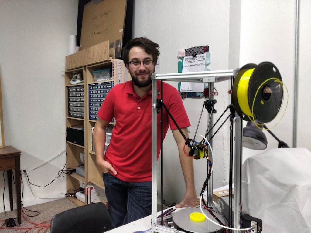
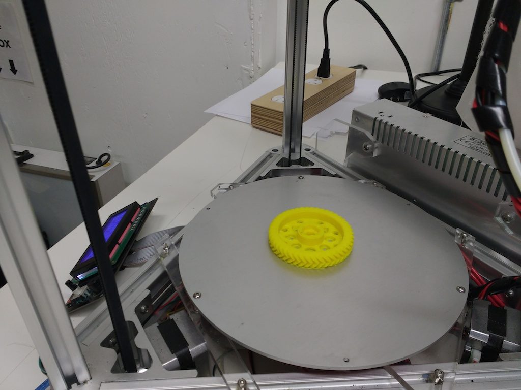
But the highlight of the night was James’ new Delta printer! James has been working on it for a few months and is starting to get pretty good prints, but still has a little tuning to do. Congratulations James!

3dpm-james-delta-sample

Fixing the Fusion 360 parametric box

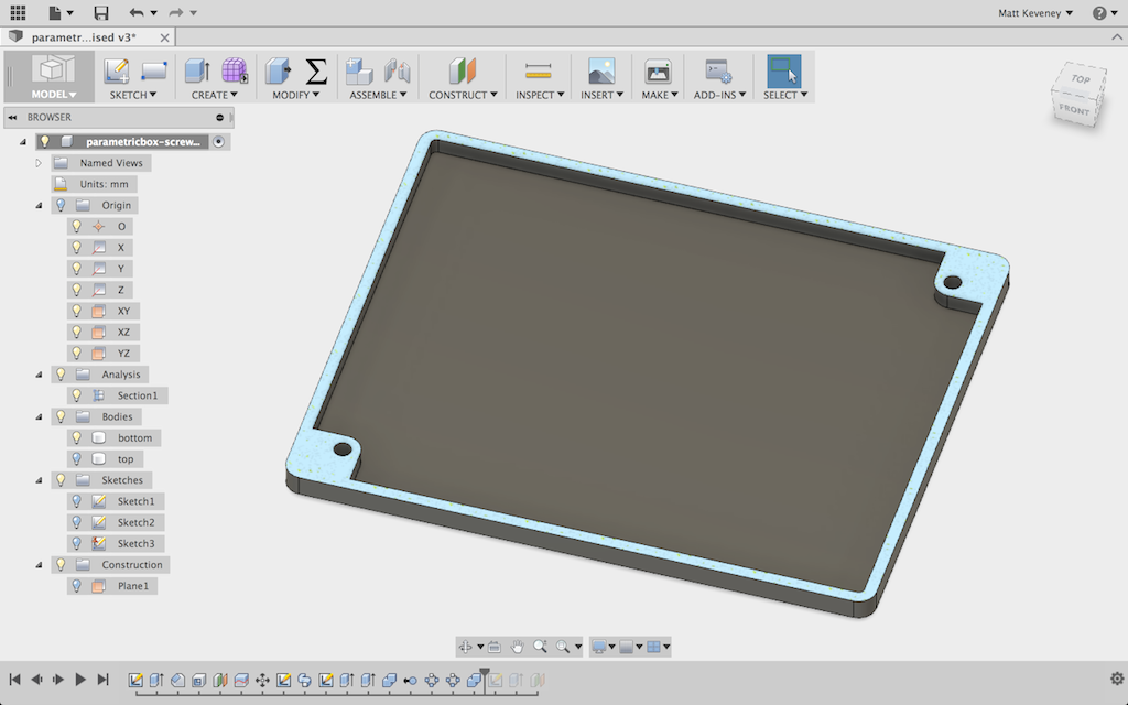
Last night’s cool Fusion 360 class inspired me to follow-up on my parametric box article. I found a bug in one of my designs not long after posting it. Fixing the bug illustrates a few interesting Fusion 360 features in its own right, so I thought I’d give a bit more detail than simply uploading a repaired model.

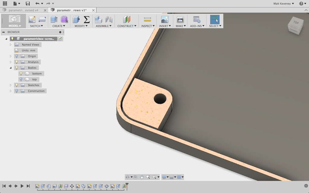
The version for screws is the one that’s broken. Recall that I created a sketch for the screw pillars on the bottom of the box and then extruded it upward to create the pillars and some support structure that attaches them to the sides of the box.

To better illustrate what’s wrong, I’ll create a section analysis. This gives us a cutaway view of the model, without actually cutting it into pieces. I can keep this analysis as part of my design and show or hide it whenever I like.

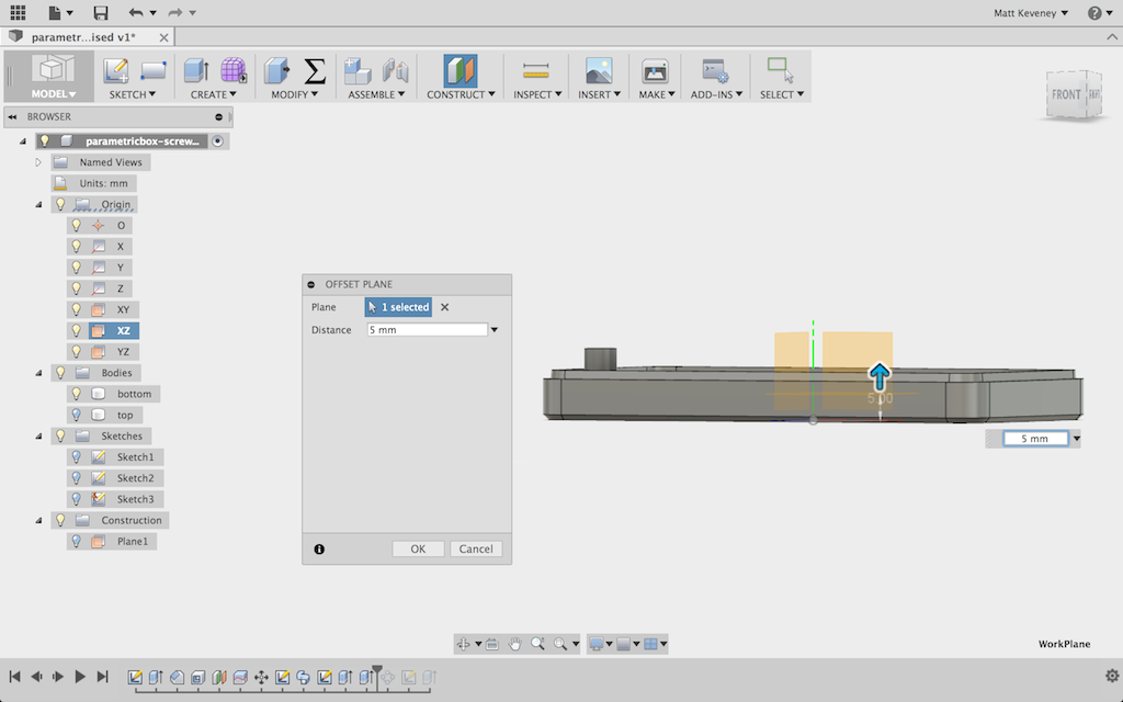
I start by creating a work plane parallel to the XZ plane, but offset 5mm up.

pbx2-offset-plane

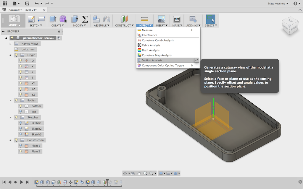
Then, I create a section analysis on that plane. This is found on the Inspect menu.

pbx2-section-analysis-menu

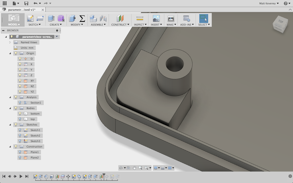
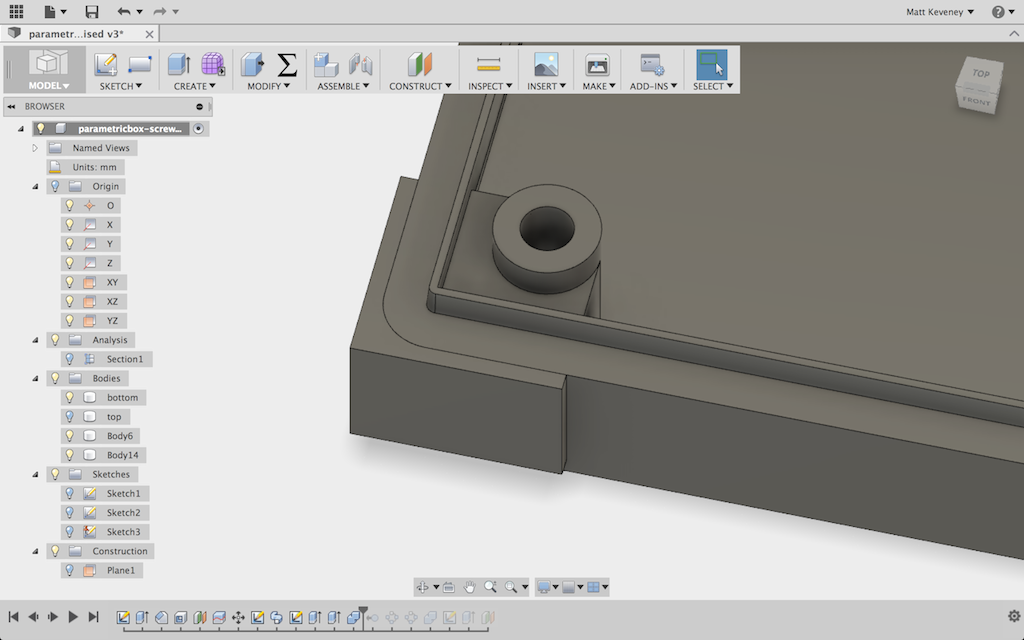
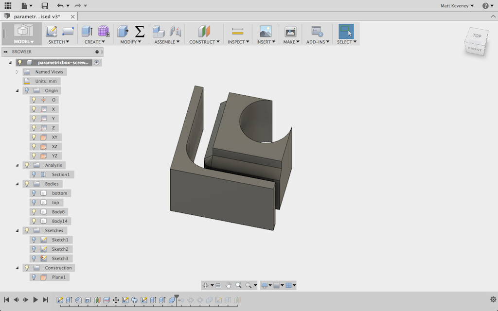
The resulting view clearly shows what’s happened. Note that the support structure does not reach all the way to the sides of the box. The chamfered corners of the box make the reinforcement just a bit too small to reach into the edges.

pbx2-original-section-analysis

If I set the chamferDepth parameter to 3mm the problem is much more pronounced. I can even see it with the section analysis turned off.

pbx2-3mm-shows-problem

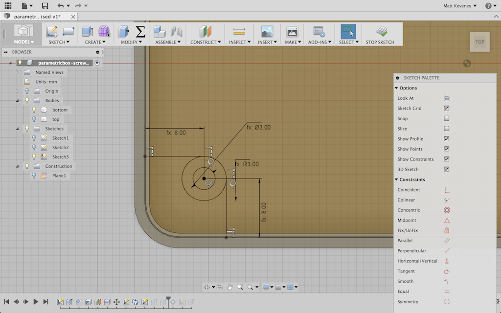
So, how to fix this? The problem is that the sketch defining the profile for the pillar support ends at the perimeter of the inside box bottom.

pbx2-original-pillar-sketch

I could simply extend it to the inside or outside wall surface, but then a portion of the extrusion would end up outside the box when defined with a large chamferDepth.

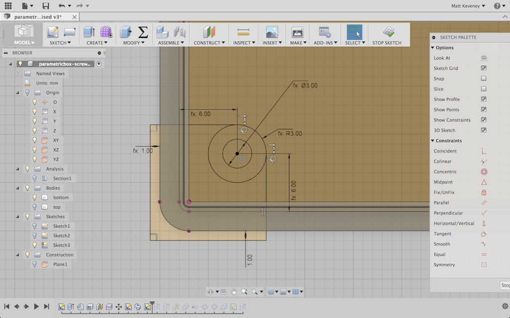
After a bit of experimentation I came up with the following. The reinforcement is designed to deliberately extend outside the outer perimeter of the box by 1mm.

pbx2-new-pillar-sketch

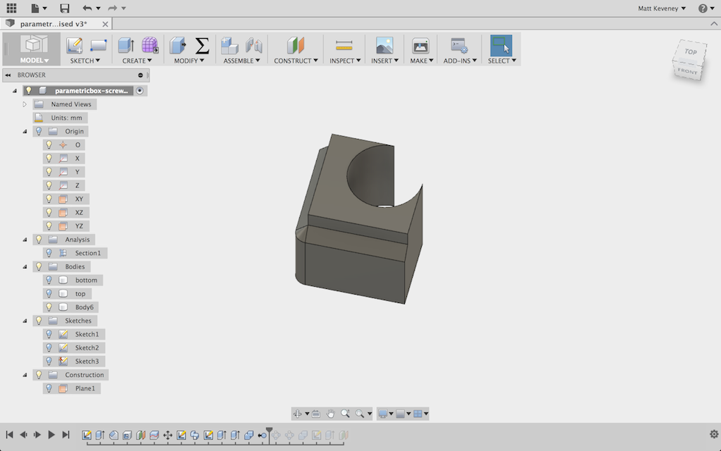
Then, I extrude it to a separate body and cut it, using the box as the tool.  I extended the body by 1mm in the last step to ensure that I always do get two pieces; otherwise the next operation is unreliable.

pbx2-reinforcment-extruded

pbx2-reinforcement-cut

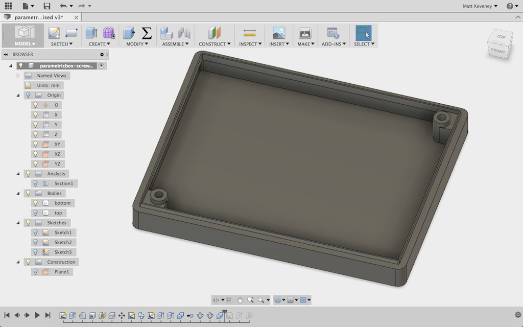
I then remove the outer portion, join the inner portion with the box bottom and duplicate with a circular pattern as before.

pbx2-reinforcement-innerpart

pbx2-new box bottom

Unhiding the analysis now shows that the originally desired structure is in place.


pbx2-new-section-analysisThat all may seem a bit convoluted, but it now seems to work with any reasonable set of parameters. A much simpler solution would have been to eliminate the chamfer altogether, or make it a small fixed dimension that would have avoided the problem in the first place.

Download the fixed version here: parametricbox-screws-fixed.f3d

-Matt


Tool Board

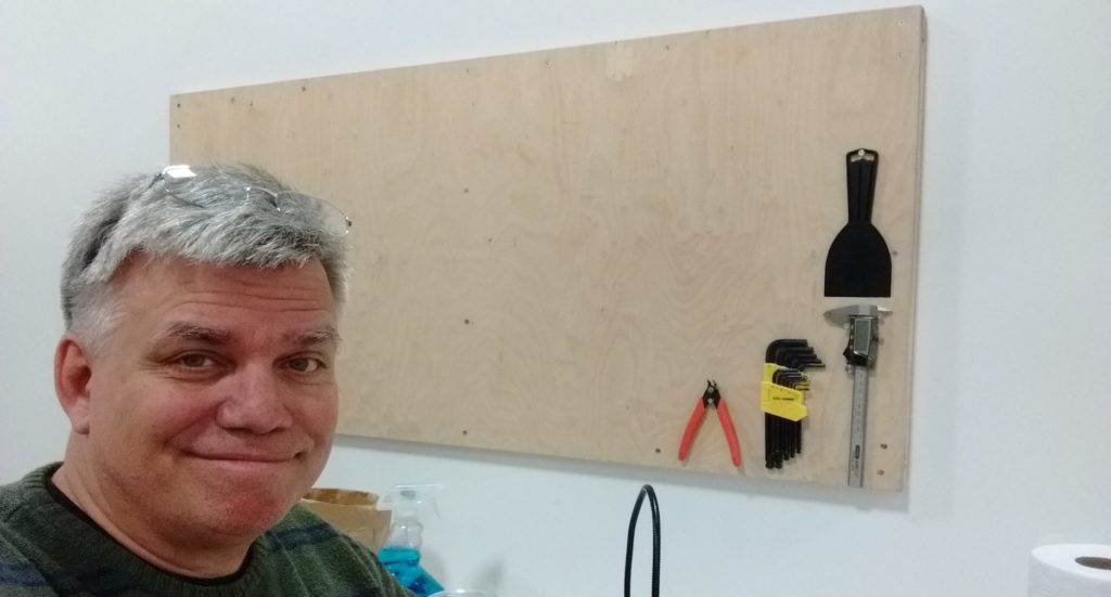
I wanted to hang my most-used tools on the wall just over my workbench/desk.

Pegboard might seem like the obvious choice, but I’ve never really liked it: The hole grid dictates positions that never seem quite right, and there’s always some tool that just doesn’t work with the standard pegboard hardware. Also, that hardware can be surprisingly expensive once you get everything you need (and the extra parts you think you’ll need but never use).

At the other end of the spectrum live craftsmen who create a custom holder for each tool, complete with six coats of varnish and an elaborate french-cleat mount system. I don’t live there. Not even in the same town.

Instead, I just wanted a simple plywood board to host any random screws, nails, cup hooks, or screw eyes that do the job. Whenever the mood strikes me, I want to be able to just hang something up, without having to go find some weird hardware or make a custom fixture. I don’t want to think about it; I just want it done.

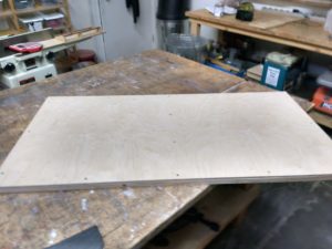
Plywood board used to make tool board
Plywood used to construct tool board

Today, in the intro to woodshop class, I spotted a 2’x4’x3/8″ plywood sheet just perfect for the job. No blue tag, so it became mine. This was my first woodworking project at AMT. I finished it in about 45 minutes this afternoon.

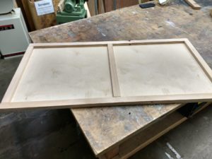
I  wanted to stiffen it and separate it from the wall in case I drive one of those cup hooks a bit too deep. I bought two 1×2 strips at the home center and made a simple frame. It’s glued and screwed to the tool board with wood glue and #8 wood screws. I have no photos of the exciting build process, since Hugh only suggested the contest after I had it done. (He gets the laptop if I win, btw. I really don’t need two.)

Strips of wood attached to plywood
Bracing added to back of board

The only power tools I used were the chop saw and two drills: One to drill pilot holes and the other to drive screws. Sure speeds things up. This is the kind of project that could be done at home, but it’s just so much nicer to work on a proper bench with enough clamps to hand, the extra drill, etc.

Back at my workshop/office, I discovered I no longer have a stud finder. Must’ve given that away in my
Tools hanging on boardmost recent purge of extraneous stuff. I borrowed a magnet from the fridge and hung it from a piece of string… which actually seemed to work better than the old stud finder. Two 3″ #8 screws hold my
board up. It seems very solid, but as I add things it might get heavy, so I’m thinking about adding a couple more. I drilled clearance holes in my board for the mounting screws, so the threads only bite into the wall studs. This way the screws can cinch the board up snug to the wall.

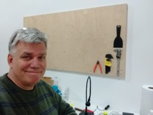
Man with tool board
Mat and his tool board

As you can see, I only have a few things hung so far, all with 3/4″ #6 wood screws. It took me about two minutes to do that much; I just drove the screws straight into the plywood without even bothering to drill pilot holes. The caliper is a good example of a tool that would not be convenient to hang on a pegboard, yet two screws do the job nicely on my tool board.

I still have a big mess to clean up, but I already like my tool board better than any I’ve used before. It feels nice to undercomplicate something for a change.


3D print meeting wrap-up, June 27, 2016

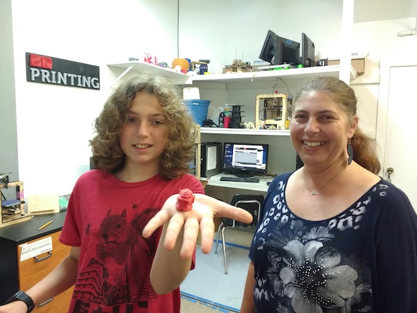
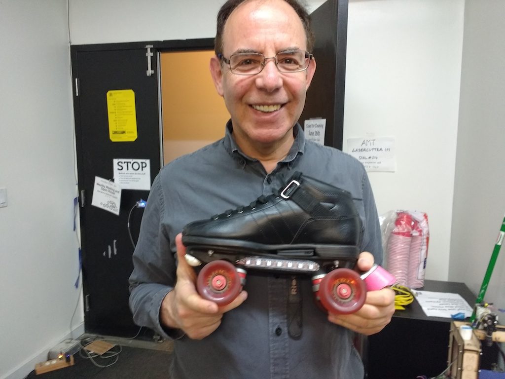
Five guests made tonight’s 3D print meeting another fun gathering. Newcomers Panos and Phil were here to see what it’s all about, new members Casper and Jaylen came by for more practice with the Replicator 2, and veteran Enric showed up with his cool blinky roller skates again; now controllable by WiFi!

Panos would like us all to know about the company he works for: Fictiv.com. I understand that they facilitate commercial 3D printing and other CAM manufacturing by ensuring that the designs submitted meet reasonable specifications. Then they turn the work over to third party shops that actually own and operate the machines. I won’t post his e-mail address on the web, but let me know if you want to contact him (or maybe try their website).

3dpm-ray

Ray popped down to show us what he’s done with one of the orphan Cupcake CNC printers I put up for grabs. The X/Y motion component was perfect for his new laser engraver! …I’m sure we can expect a full report from Ray once the project is complete so I won’t say more, except that it’s great to see someone breathe new life into old hardware.

3dpm-casper-jaylen

Jaylen found a cool model on Thingiverse. It’s some kind of space-age looking helmet–you’ll have to ask him about the details. We made it exist with the Replicator 2. The author of that model had apparently never printed it before so this might just be the first physical rendition the universe has ever seen.  Unfortunately, the experimental nature also meant there’s lots of nasty support material to remove. Ugh!  Good luck Jaylen!

3dpm-pendant

Then, we adjourned to the next room for another off-the-cuff demo of modeling with Fusion 360. This is much more fun with the cool new projector! Casper was first to respond to my invitation to shout out an idea for a new thing… unfortunately it was the kind of thing I’m not terribly good at: “some kind of pendant,” she said. <sigh>.

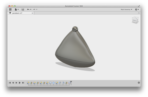
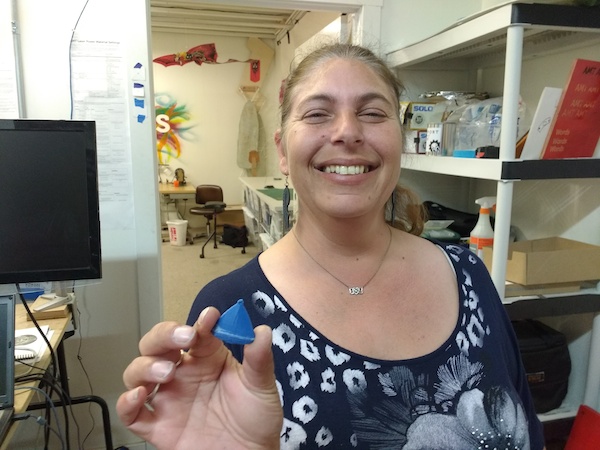
But I gave it a shot using Fusion’s loft tool (in retrospect, the sculpt mode might have been a better choice). Nobody has ever accused me of being artsy, but we got something passable thrown together; sliced it in two for easier printing; then printed it on my delta and glued it together.

3dpm-phil-delta

It’s always fun to go from “idea” to “thing” in just a few minutes (even if you don’t identify as artsy).

3dpm-caspers-pendant

Here’s the Fusion360 model in case anyone wants to see how it was done.

The homely pendant

And here’s Enric, just posing like a goofball in case you’d rather see how that’s done.

3dpm-enric

-Matt

A parametric design for 3D printed boxes

…and my thoughts on filament quality.

3D printing presents some special challenges when designing parts that must fit together. In this article I’ll explore this briefly while creating a simple plastic box with a close-fitting lid. I’ll try to make the design as flexible as possible, using Fusion 360’s parametric features.

A simple rectangular box is what I’m after. The top of the box will fit over an interior lip designed into the bottom. The side faces of the top and bottom will be flush with one another when the top is on. The vertical corners of the box will be rounded. The edges along the upper and lower face will be chamfered.

For starters, I’ll add user parameters for the features I know I want to be adjustable. I can always add more as needs arise. I’ll initialize my parameters to something that seems reasonable.
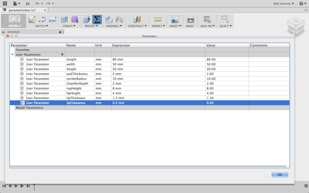
pb_parameters

I’ll model a solid box and use the shell tool to hollow it out. Then I’ll use the split tool to cut off the top. I start with a sketch of the perimeter of the box, viewed from the top. Note that my dimensions reference the parameters I just entered. Note also that I draw the box centered around the origin. This will come in handy later.
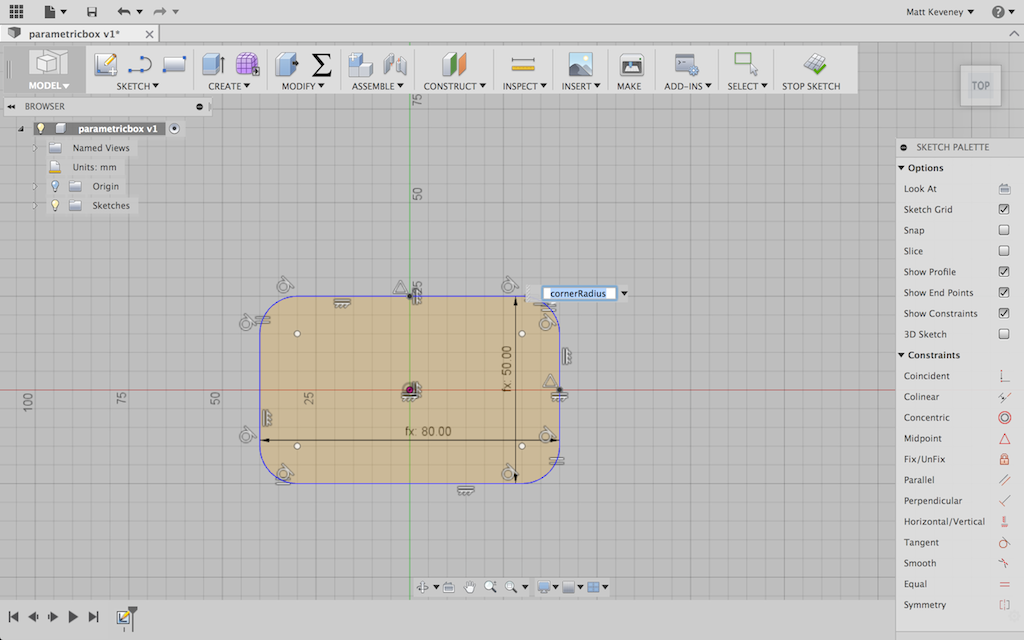
pb_bottomsketch

I extrude this to create the box. For the extrude height, I reference my height parameter.
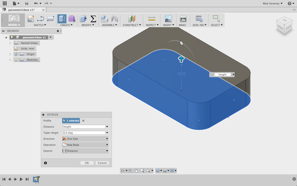
pb_boxextrude

Next I chamfer the top and bottom edges. I can select all the edges and apply a single chamfer operation. It’s important to apply this before hollowing out the box, since the chamfers might excessively thin the material at the corner or even cut through.
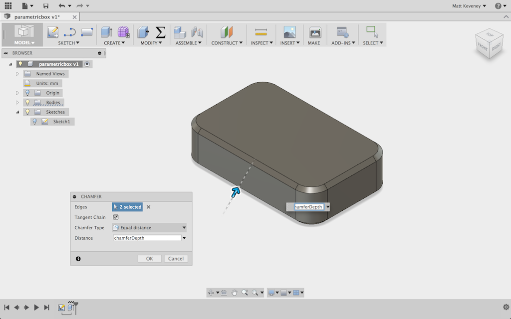
pb_chamfered

Now I’ll hollow out the box using the _shell_ tool. Since I want an internal cavity, I select the entire body.
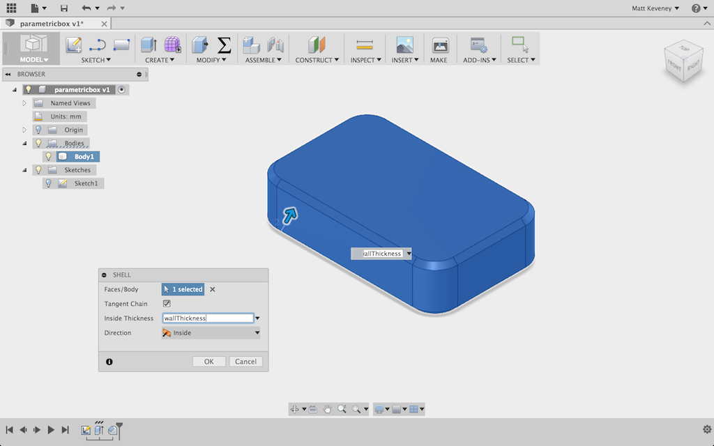
pb_shelled

I’ll briefly switch to wireframe view to confirm that the inside has been hollowed out.
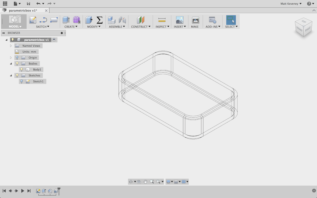
pb_shelled_wireframe

Now, I make a construction plane offset downward from the top of the box by the height of the box top.
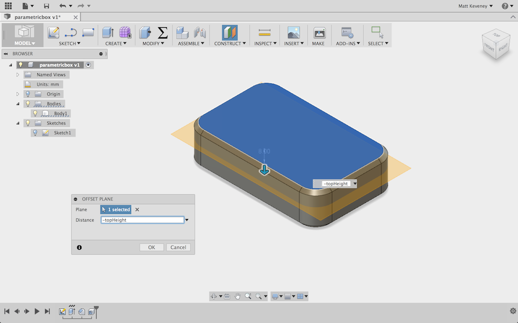
pb_workplane

I use the Split body tool to separate the top from the bottom.
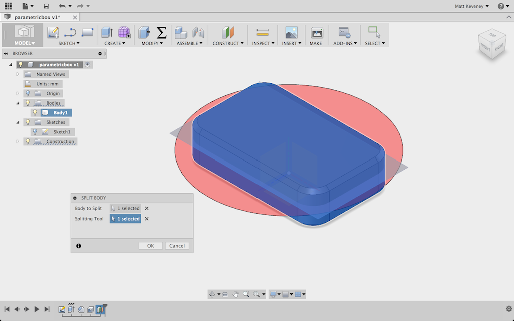
pb_split

It’s a good idea to give the bodies functional names at least. If I were doing more extensive work with this box, it would make sense to put the top and bottom into separate components too, but I’ll skip that for today.
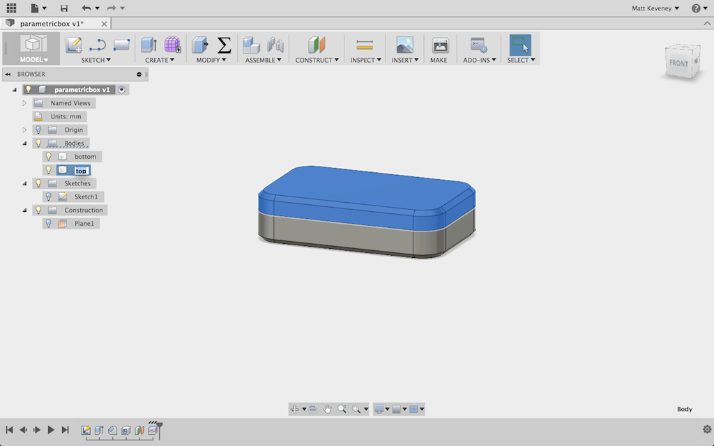
pb_bodiesnamed

Now, just so I can see what I’m doing, I’ll move the box top up a bit. I’ll re-use the lip height for this dimension.
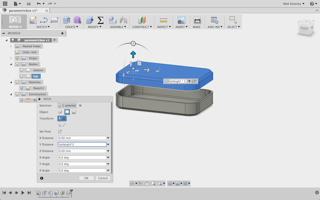
pb_topmoved

This is a good place to stop and check that the parameters actually work. I’ll make a few changes and visually check that the model seems to respect them. Here’s a wide, flat version:
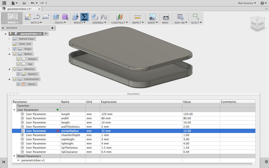
pb_wideflat

And a tall, narrow version:

pb_tallnarrow

Now to tackle the lip. I want the lip to project inside the box bottom and to leave a bit of clearance so that the box fits nicely. I don’t want the lip to extend all the way to the bottom of the box, so I’ll create a sloped face on its bottom edge to eliminate the sharp overhang. I hide the top first. Now, since I had the forethought to center my box, I can create my sketch on the default XY plane.

I then project the intersection of the top right inside corner and anchor the rest of the profile to it. Note particularly the small horizontal segment dimensioned to the ‘clearance’ value. I’ll adjust this parameter experimentally to get a good fit.
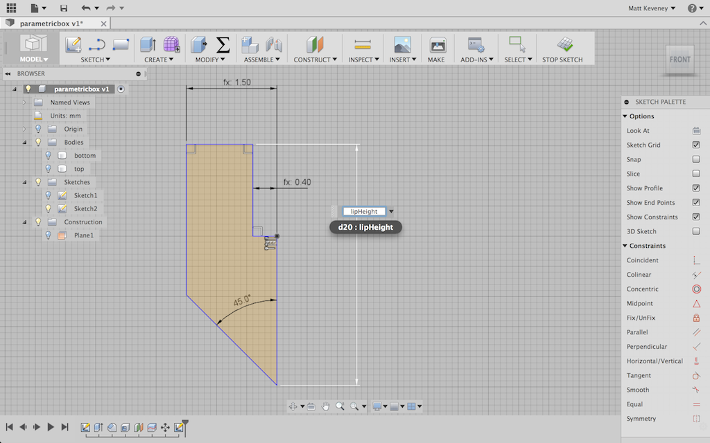
pb_lipsketch

With the profile done, I use the sweep tool, specifying the top inside edge of the box as the path.
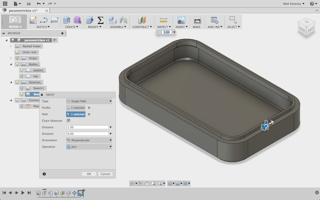
pb_lipswept

My box model is complete; now the tweaking begins. I just guessed at the initial clearance value of 0.4mm, since that size has worked reasonably well in the past. But I also know from experience that I can’t predict this perfectly. Even though the mechanism of my printer is very accurate, the final part dimensions can still vary due to slight inconsistencies in filament width, differing filament temperatures, slicer settings, etc.
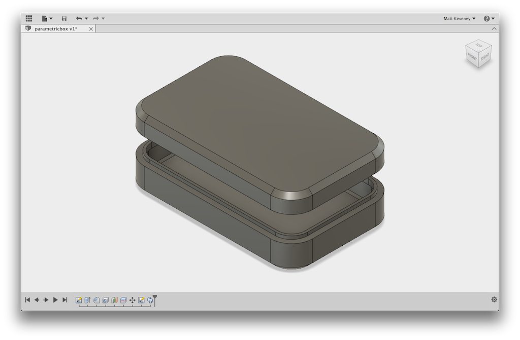
pb_complete

Now for a bit of a diversion: Whenever I discuss dimensional tolerances, someone inevitably asks whether “high quality” (read: expensive) filament will solve the problem. Certainly the premium filament vendors would like you to think so, but it isn’t true in my experience. No matter how much I spend, I see variations in filament diameter and melting temperature that are significant enough to cause slight variations in part dimensions.

I now use inexpensive filament mostly from vendors on eBay. I choose vendors with a reasonable level of positive feedback, and have had very good luck lately (14 spools purchased over the last 8 months or so; all work well; most under $19.00/kilo including shipping). When I did choose a more expensive vendor (still just $22.00/kilo), it was only because the cheaper places didn’t have the colors I wanted!
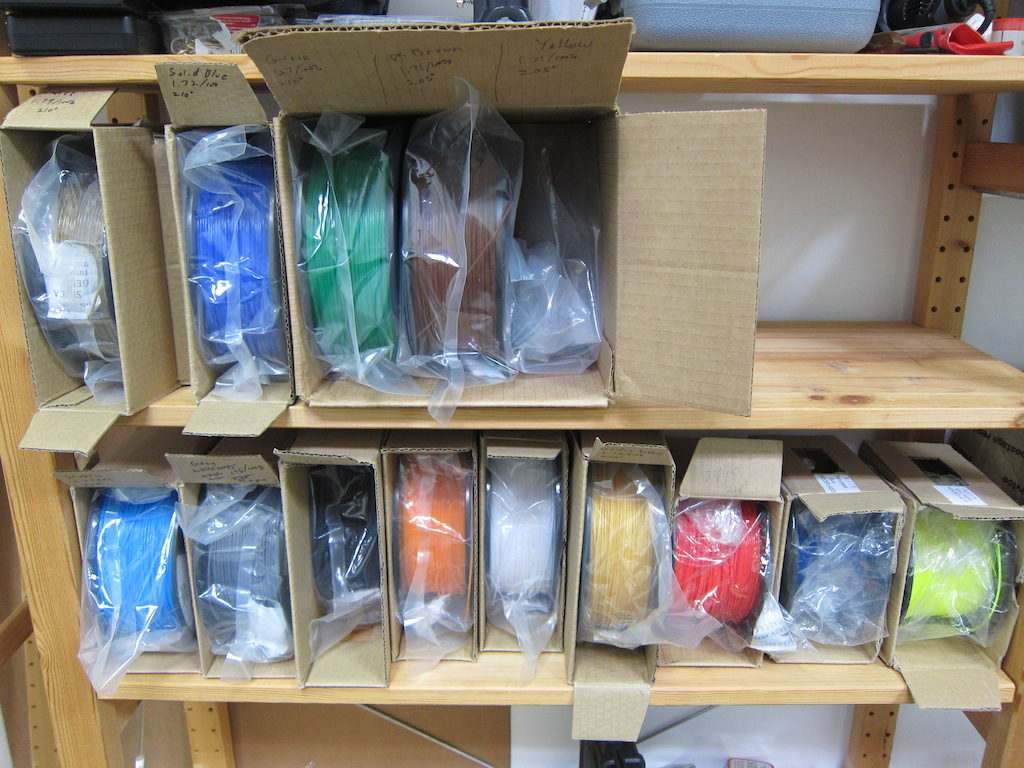
pb_filaments

I think that filament quality in general has improved in recent years.  Here’s a fairly current review of some cheap filament from Hobbyking that seems to agree (Hobbyking is currently selling $10.00 spools that have just 1/2 kilo, so be sure to compare fairly). I think the situation was worse a few years back, so check the dates on what you read.

I also think that some of the complaints may be from folks venting their frustration instead of acknowledging the simple fact that all manufacturing technologies are imperfect.

Instead, we can learn to work within the limits of the technology, including variations in filament properties. To help with consistency, I always measure my filament diameter and record it along with the temperature and any other non-default slicer settings.
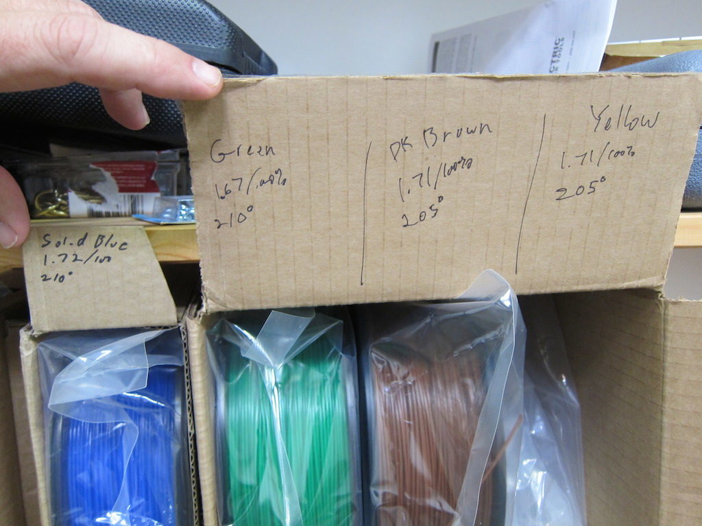
pb_filamentsettings

Even with all that preparation, a really close fit always seems to require some experimentation. Rather than fight it, I design my parts to accommodate these experiments with a minimum waste of time and material. Sometimes I make an abbreviated copy of the part so I can test the fit without printing the entire thing out. The following screenshot is the model I used to print the scoop for our dart-scooping-robot at MakerFaire. The model on the right is the abbreviated version I tested before committing to the five-hour print on the left.
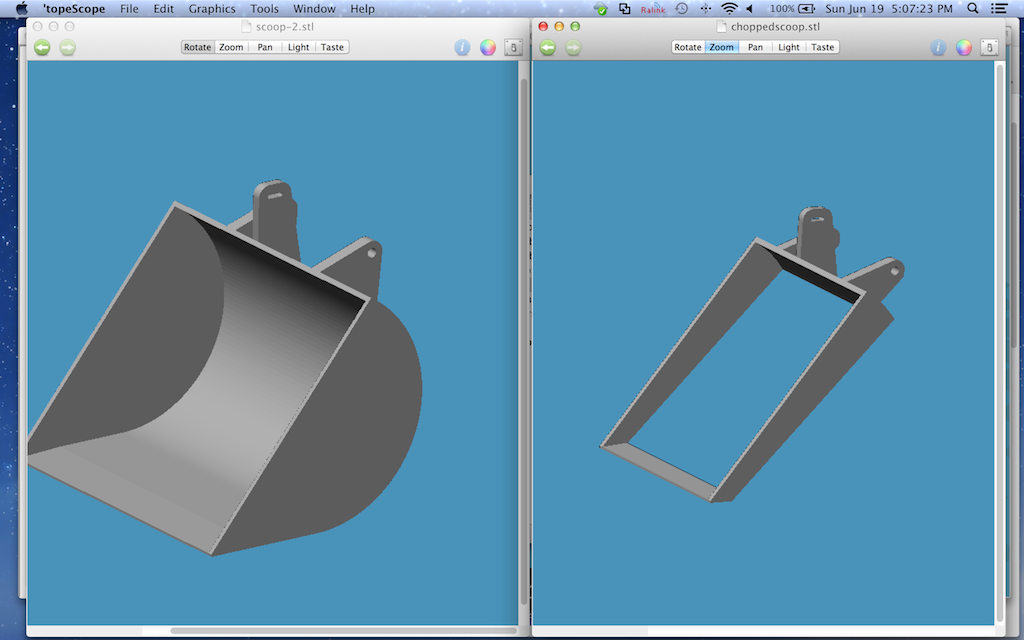
pb_scoops

Of course, the best strategy might be to design your work in such a way that a close fit is not necessary at all! More on that later. For now I’ll proceed with the experimental technique.

Since I’ve made this box parametric, I can simply enter parameters for a smaller box! Once I figure out the proper clearance value for my filament and slicer settings, it ought to remain valid for any size box.

So, let’s start with a very small box: 30x30x10, using my initial guess for clearance of 0.4mm.
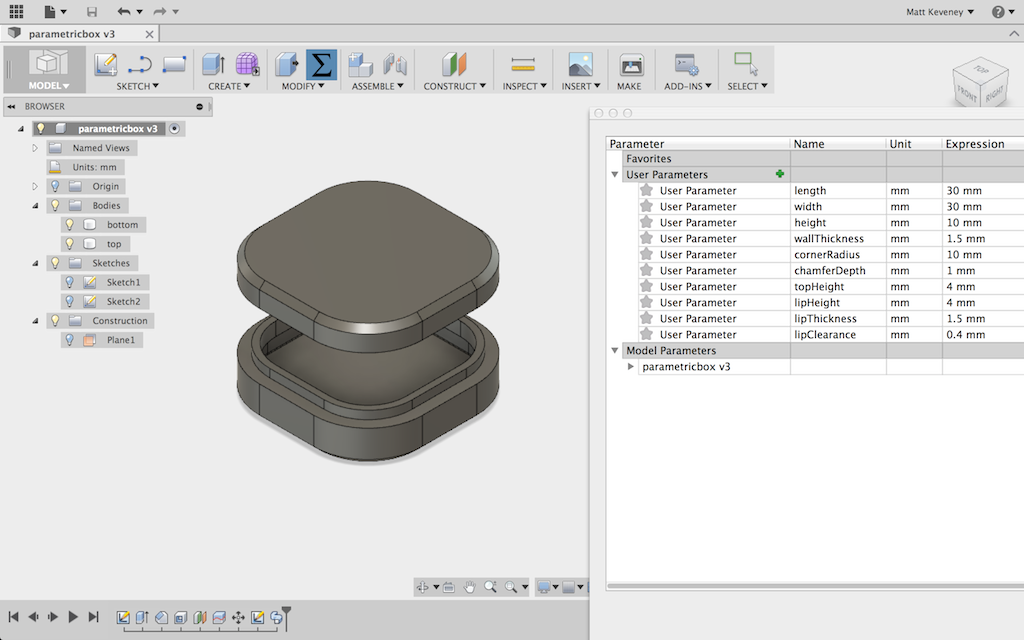
pb_30x30_04

pb_test1

Well, that gave me reasonably good results on the very first try. The top fits, but might actually be a wee bit too tight. I’ll try again, increasing clearance to 0.5. I’ll also see if I can go with a wall and lip thickness of just 1mm, and I think I had the temperature a bit too high, so I’ll adjust that too. A more scientific approach would be to modify just one variable at a time, but I think I can get away with breaking that rule here.
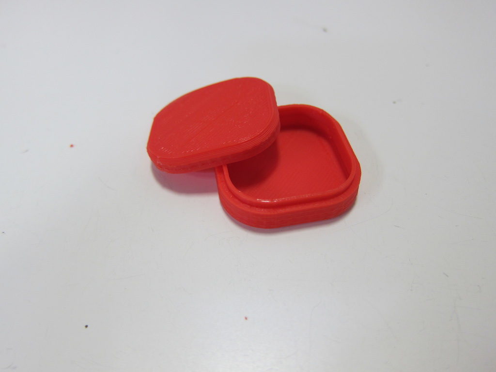
pb_test2

Looks good; the new wall thickness is fine. The lid fits with a bit of wiggle room and no longer snaps in place. For a good friction fit, I think something closer to 0.4 than 0.5 would be about right for the clearance parameter. I’m confident enough at this point to try something bigger: 80x60x25.
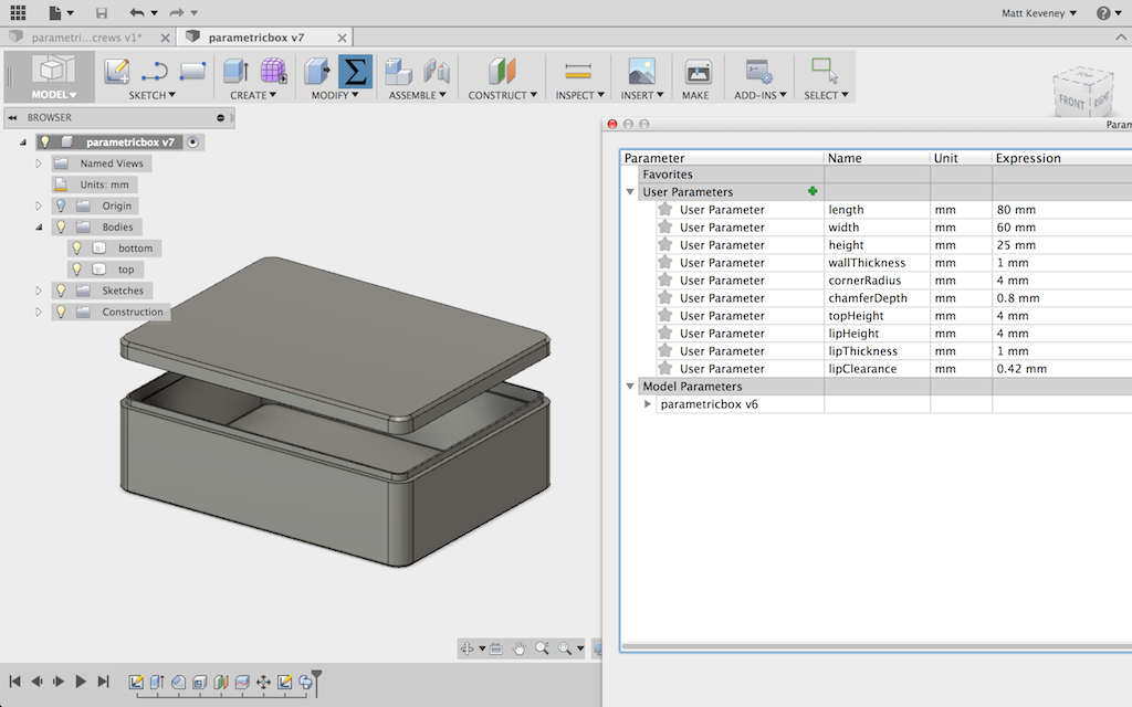
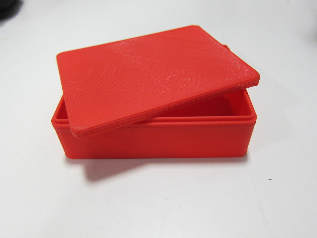
pb_80x60x25_042

pb80x60x25

And it works great.

Instead of doing all that work to get a close interference fit, I can just use screws to fasten the box together. I could eliminate the lip altogether and rely on the screws to align the top and bottom, but I’ll keep the lip, modifying the profile so that the mating face slopes slightly inward. Now, the lip serves merely to align the top as it is fastened in place.
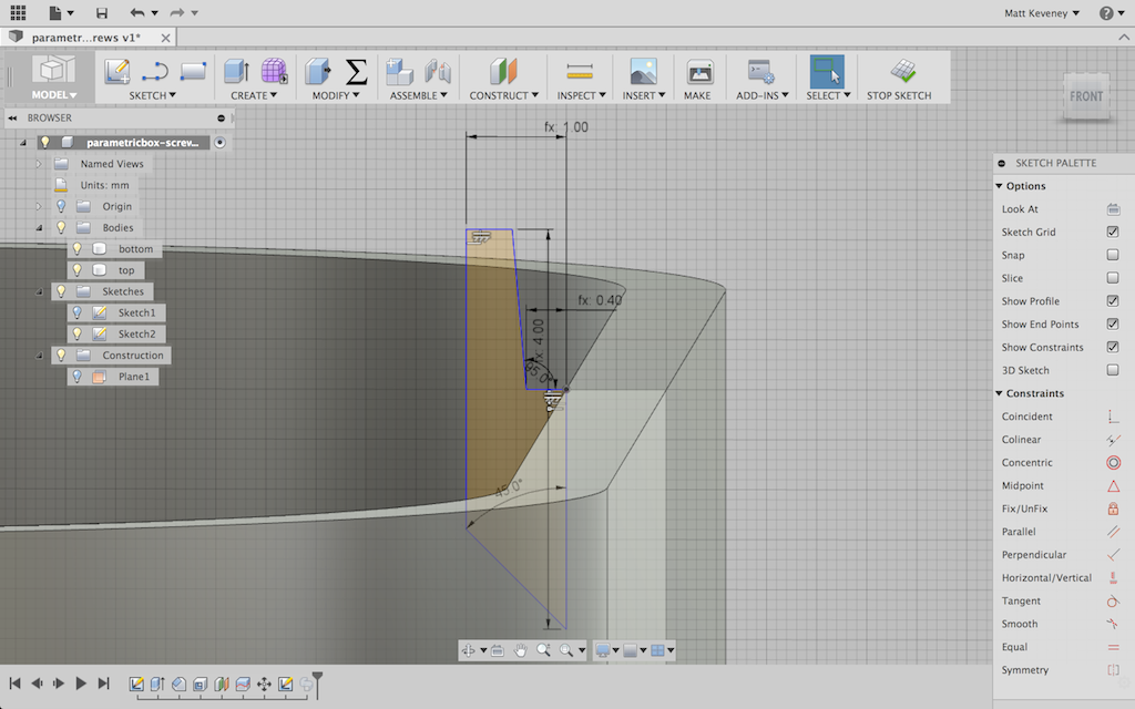
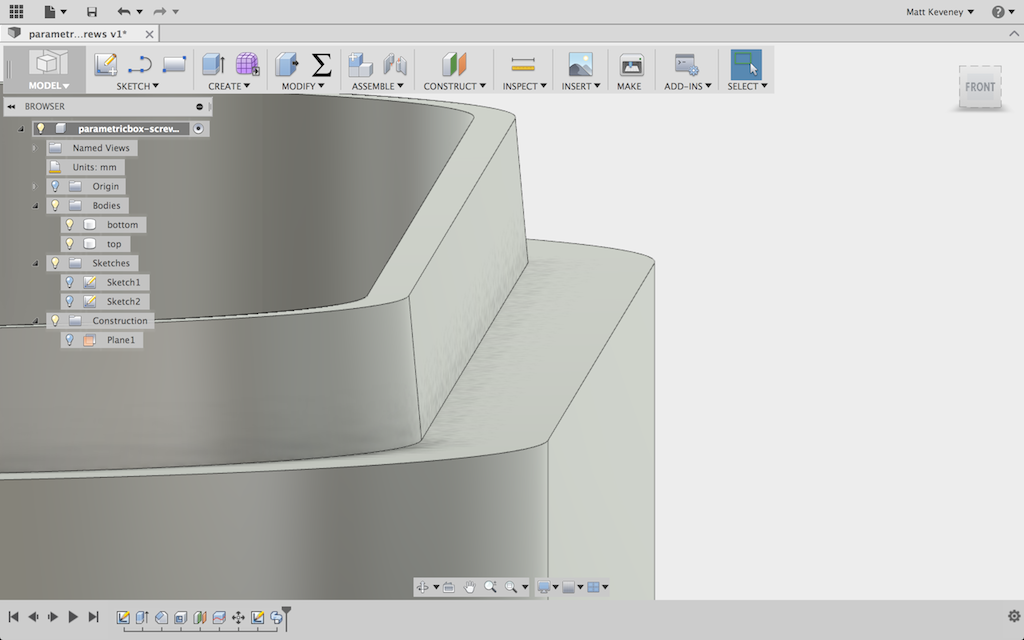
pb_slopedprofile pb_slopedlip

I’ll design for two of these these self-tapping screws in opposite corners of the box. They require a smaller hole in the bottom, where the threads bite in, and a larger hole in the top. If you get the hole sizes right, you can even get away with normal (not self tapping) machine screws.
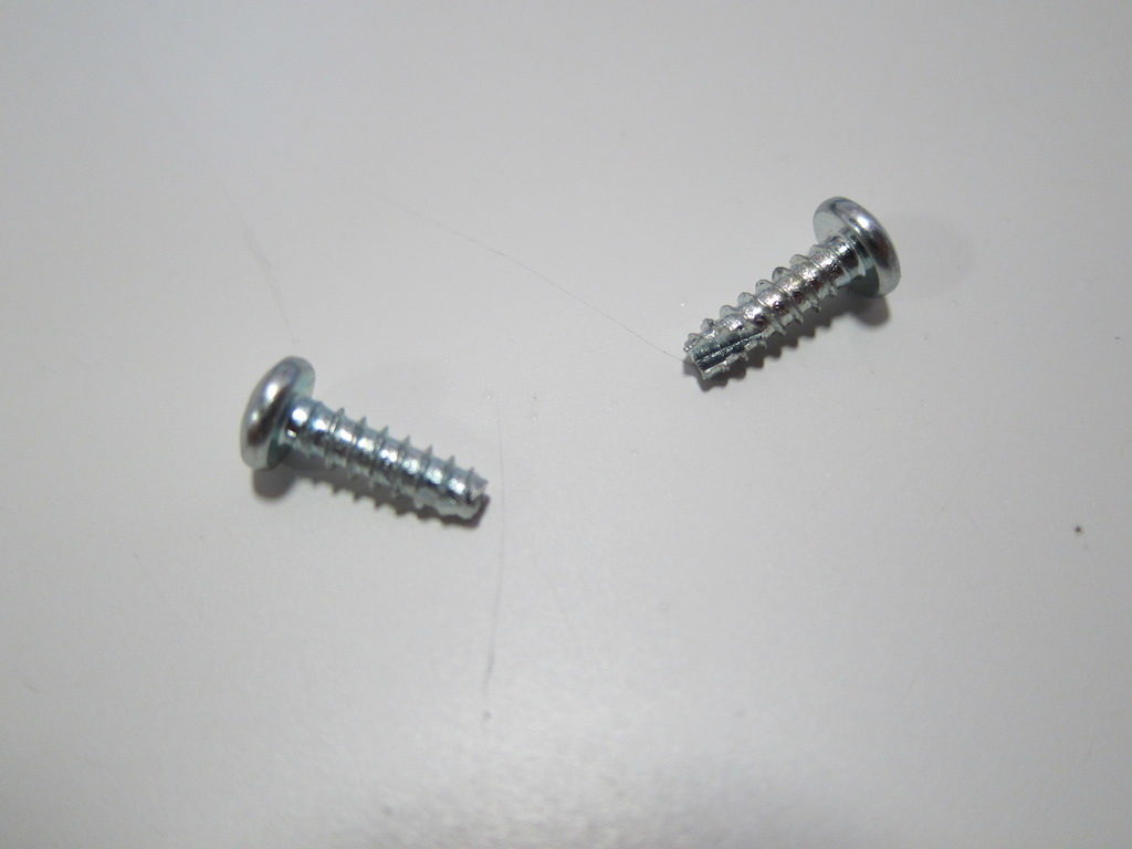
pb_stscrews

The screws are not long enough to reach to the bottom of the box, so I’ll add a boss for the screw to bite into. Since this boss is so close to the edge of the box, I’ll extend material to the sides of the box in the lower portion. Here are the parameters I’ve set up:
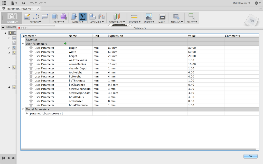
pb_bossParams

It might be tempting to center the screw right at the center of the curved corner profile, but remember that this is a parametric feature. If the curve radius is made very small, the center would not be an appropriate place for the screw. Instead, I’ll make an independent parameter to fix the screw location relative to the inside edges of the box. This way, I’ll have the option to align the screw with the corner if I like.
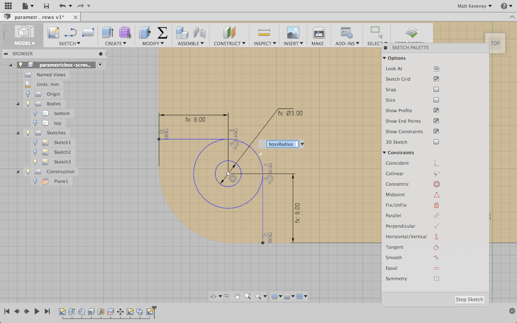
pb_boss_sketch

I’ll extrude the boss itself almost to the inside top of the box. I used a formula that didn’t show clearly in the screenshot: height – 2 * wallThickness – bossClearance.
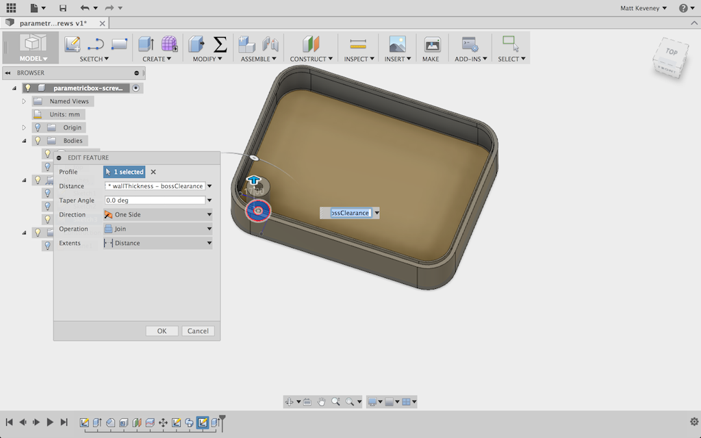
pb_bossExtrude

The reinforcement is carried up to the middle of the lip.
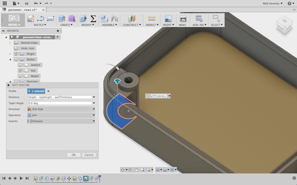
pb_bossReinforcment

Then I use the circular pattern tool to copy the boss and reinforcement to the opposite corner. Another good reason to center my part around the origin.
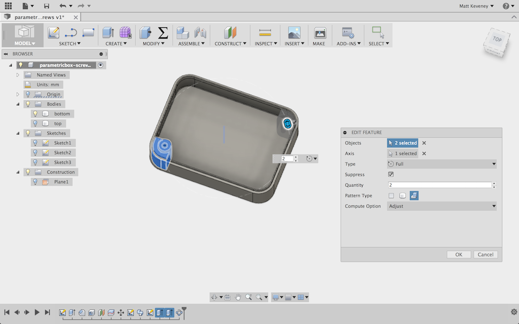
pb_otherboss

I adjusted the boss-related parameters a bit just to assure myself that they’re working properly. So far so good.
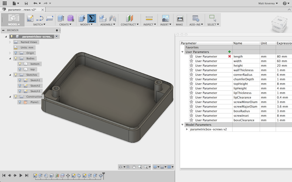
pb_newbossparams

Now, I unhide the top, create a sketch on it, and project the boss perimeters onto the sketch. Note that I’ve projected the outer boss perimeters; not the central holes. This avoids confusion with the clearance holes in the top which have a slightly larger diameter.
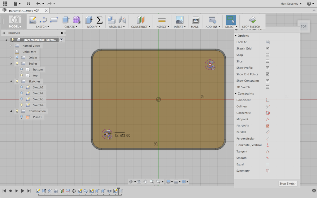
pb_top_hole_sketch

And, finally I use the press pull tool to bore the holes. I hide the bottom first, so I don’t accidentally bore the hole through both parts.
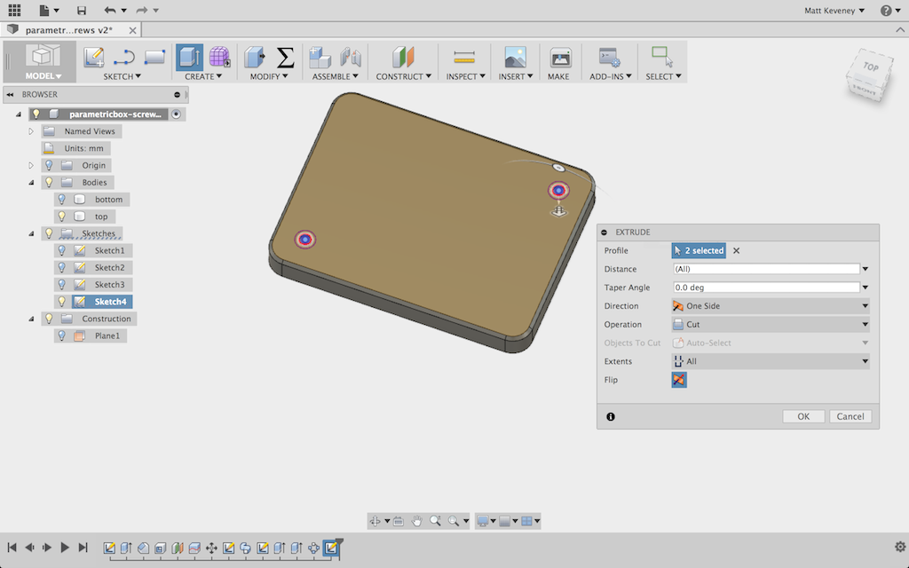
pb_top_holes_bored

A few parameter tweaks later, I’m ready to print!
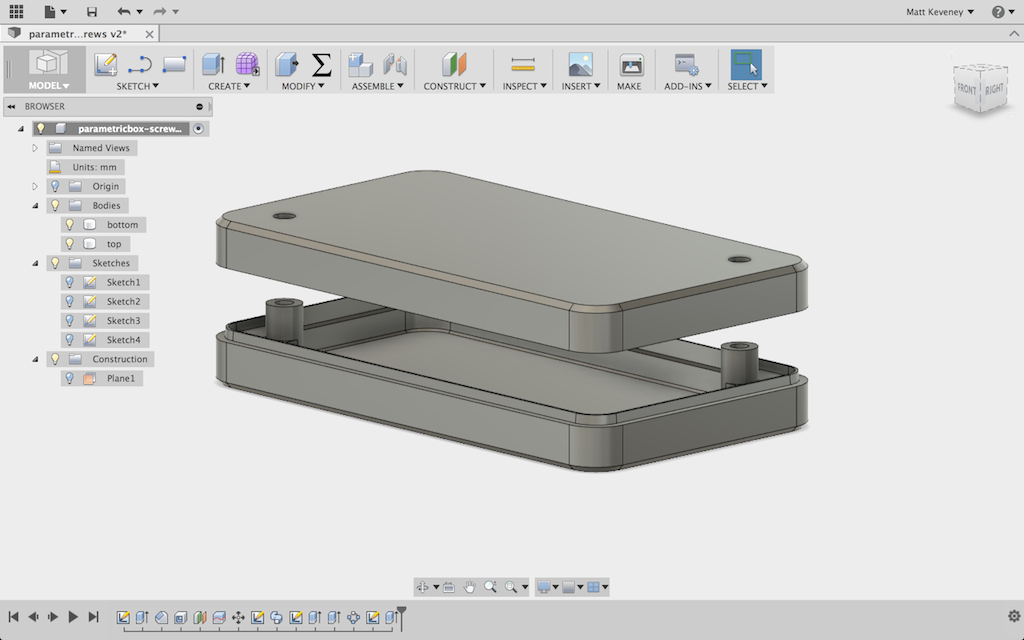
pb_holedreadytoprint

And this is the result.  You may download these models below. I’ve tried to make them as flexible as possible; I hope you find them useful!
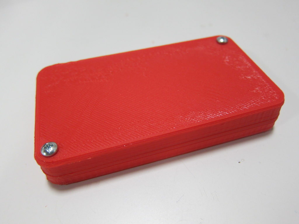
pb_withscrews

Click here to download the Fusion360 model files.

Update:

Shortly after publication, I found a bug in this model.  See my follow-up article:


3D print meeting wrap-up, June 13, 2016

We had another good 3D print gathering last night. New members Bosco, Che, and Dan attended; visitor Tony was investigating AMT, and veteran Enric brought along his latest work.

We started with a printer run through for the newbies. Che picked out a cool little Minecraft sword that we found on Thingiverse. It’s compatible with Lego characters, and is small enough to afford instant gratification.

Dan has begun working with Solidworks recently and has already modeled some impressive parts. He was off and running immediately. Dan, can we convince you to write up a project post with more detail? All members can post on the new AMT website! The parts look really interesting, and the post would be good reading even if the project is incomplete.

3dp-7-13-Dan

Enric as usual brought along one of his recent Arduino projects; LED lights for his roller skates. Enric makes custom cases for the electronics; this one fit neatly right under the skate. Enric, we’d love to see project posts from you too!

3dp-7-13-Enric

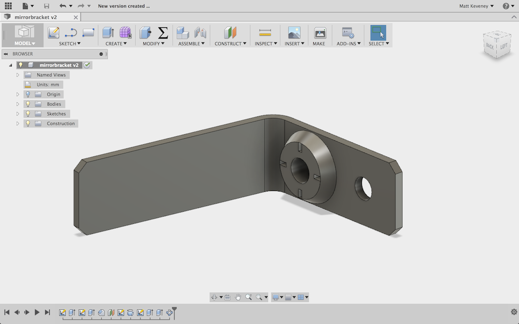
While Dan was printing away, the rest of us ducked into the classroom, hooked up the projector and brainstormed about design. I had an idea for a little bracket to hold a mirror behind my old camera so I can see the screen and shoot selfies. We got the design done, but by then it was a bit too late to print it out.

3dp-7-13-f360-bracket

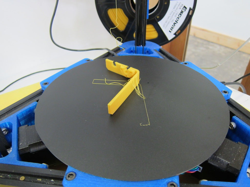
So, I just attempted to print it on my own printer. Unfortunately it got knocked off the build platform when it was about two-thirds done. <sigh> Next time I’ll use the brim feature to hold it on better.

3dp-7-13-failedprint

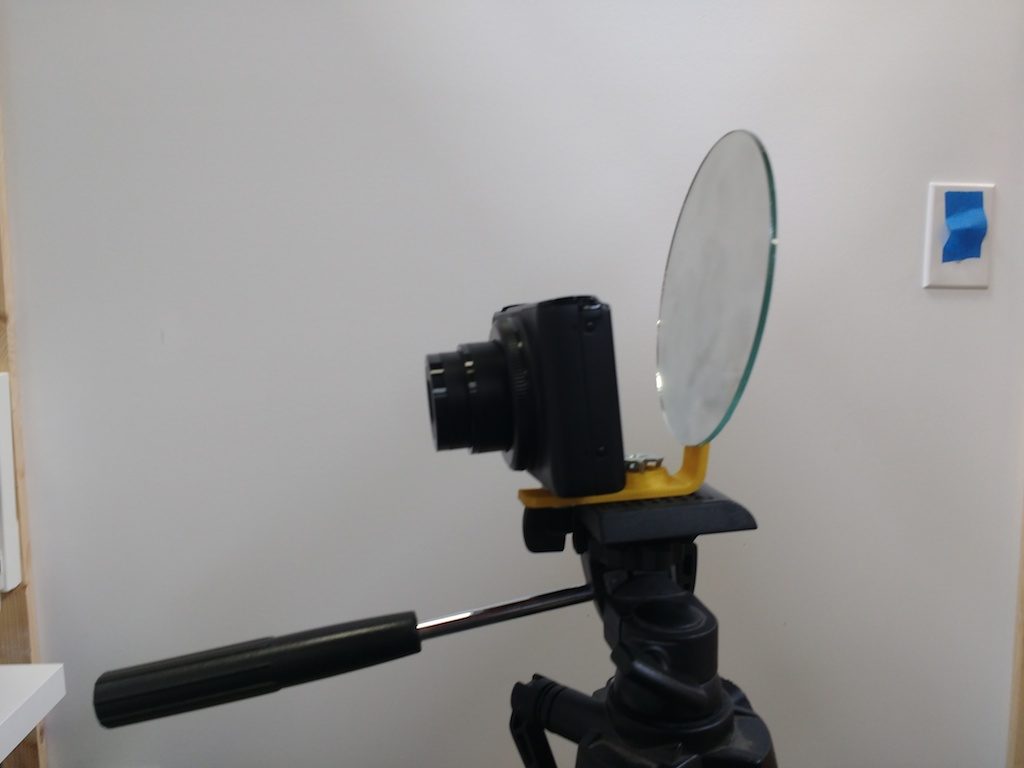
Still, enough of it printed to enable me to test it out.

3dp-7-13-ontripod

There are a few issues I want to fix before reprinting:

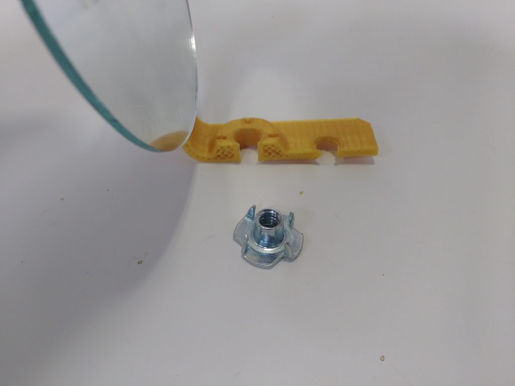
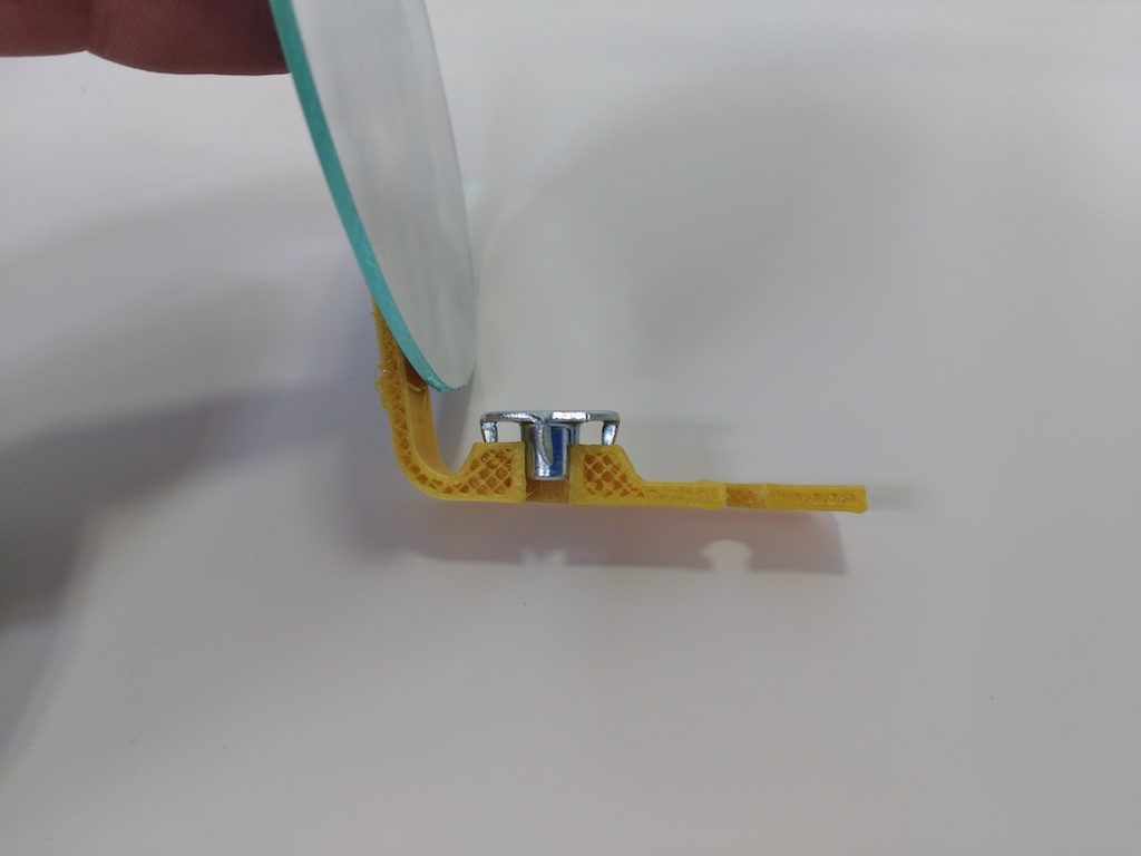
The raised boss in the middle was intended to accommodate a woodworking-style blind nut, so that the bracket could be mounted to a tripod. It has pointed teeth which are ordinarily driven into the wood to keep the nut from turning.

3dp-7-13-blindnut

We modeled slots for these teeth, which turned out to be a bit too small. Holes often have to be enlarged for 3D printing; I thought I’d done so, but evidently not enough. Also, the teeth on the blind-nut aren’t perfectly straight, so they probably require a bit of wiggle room.

3dp-7-13-nutdoesntfit

We modeled a simple hole in front to mount the camera with a screw, which I immediately found annoying. A knob would be much more convenient, preferably one that’s somehow captured with the bracket so it doesn’t get lost.

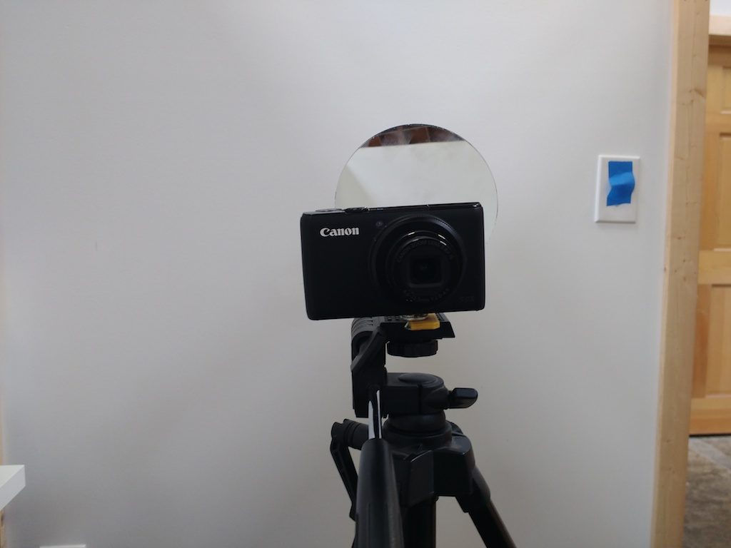
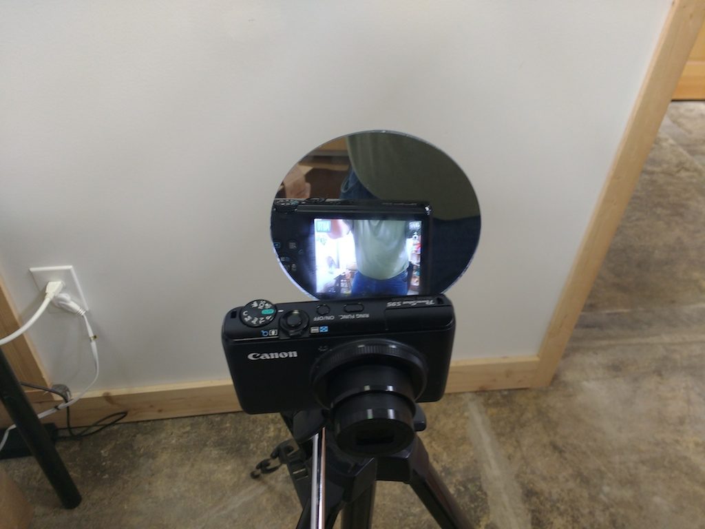
But, the biggest problem is that the geometry turned out to be all wrong. When the camera is framed properly, the mirror is hidden behind it. If I turn it enough to see the screen, the camera points at my bellybutton.

3dp-7-13-hidden

3dp-7-13-bellybutton

So, it still needs a bit of work. Maybe it would work better if the mirror was positioned to the side of the camera rather than above it…? Anyway, I’ll keep after it and post an update.

-Matt

A 3D printed replacement part

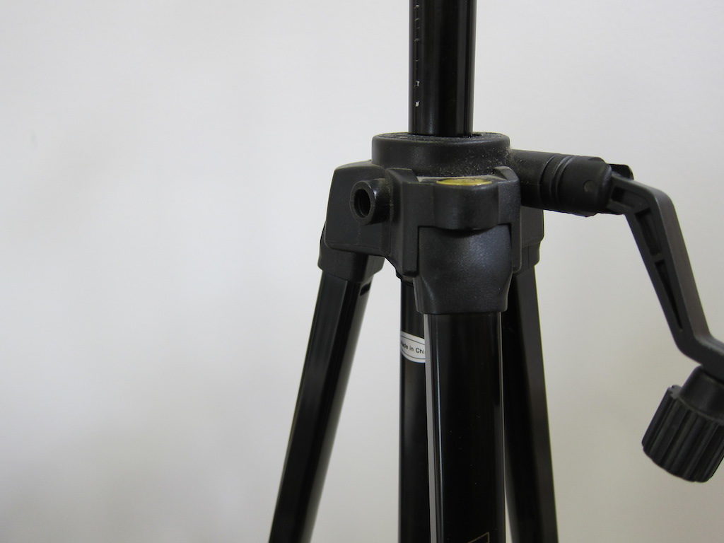
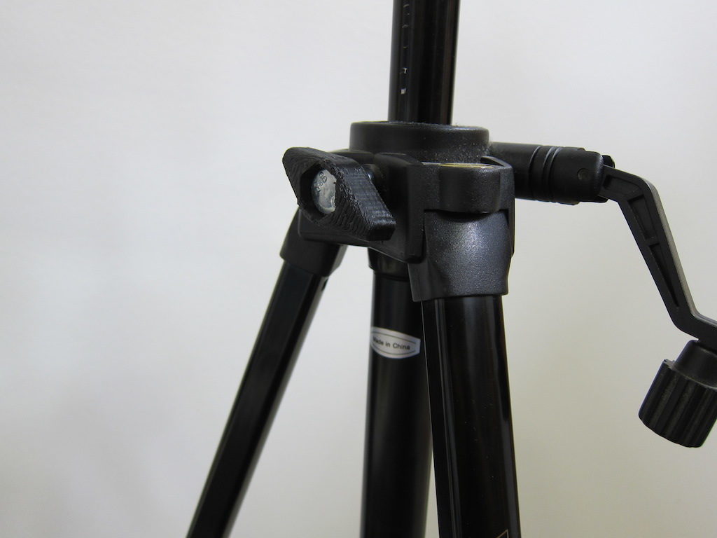
I dug my camera tripod out of storage the other day only to discover that one of the knobs has escaped. A great chance to use a 3D printer for something more than a ‘cereal box toy,’ as Hugh puts it.

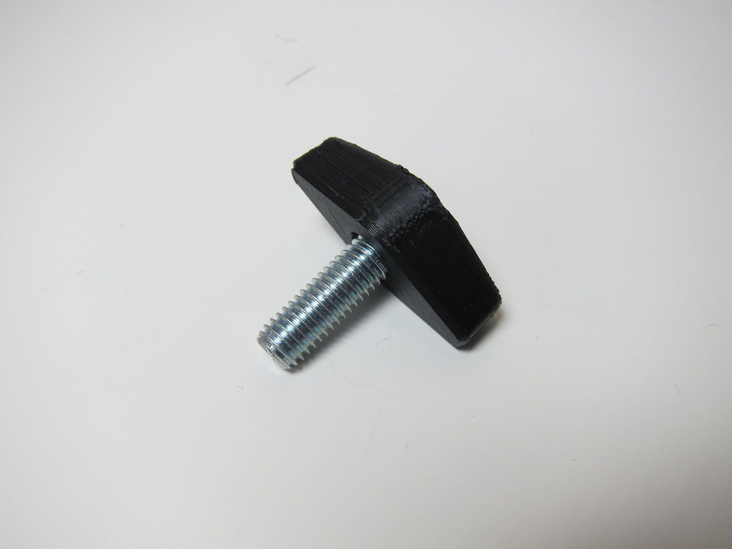
tk_missing_knobI rooted around in my Box O’ Loose Screws and found a bolt that fits. Unfortunately it’s a cap-screw type, and I was afraid my knob would slip and wear loose over time. So, I went to the hardware store and found an equivalent with a hex-head. I thought I might just be able to find a star-knob while I was there, but this turned out to be a metric size (M8). The head of my new bolt is just under 13mm across the flats, so I’ll start my design around that.
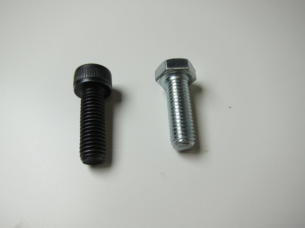
tk_two_bolts

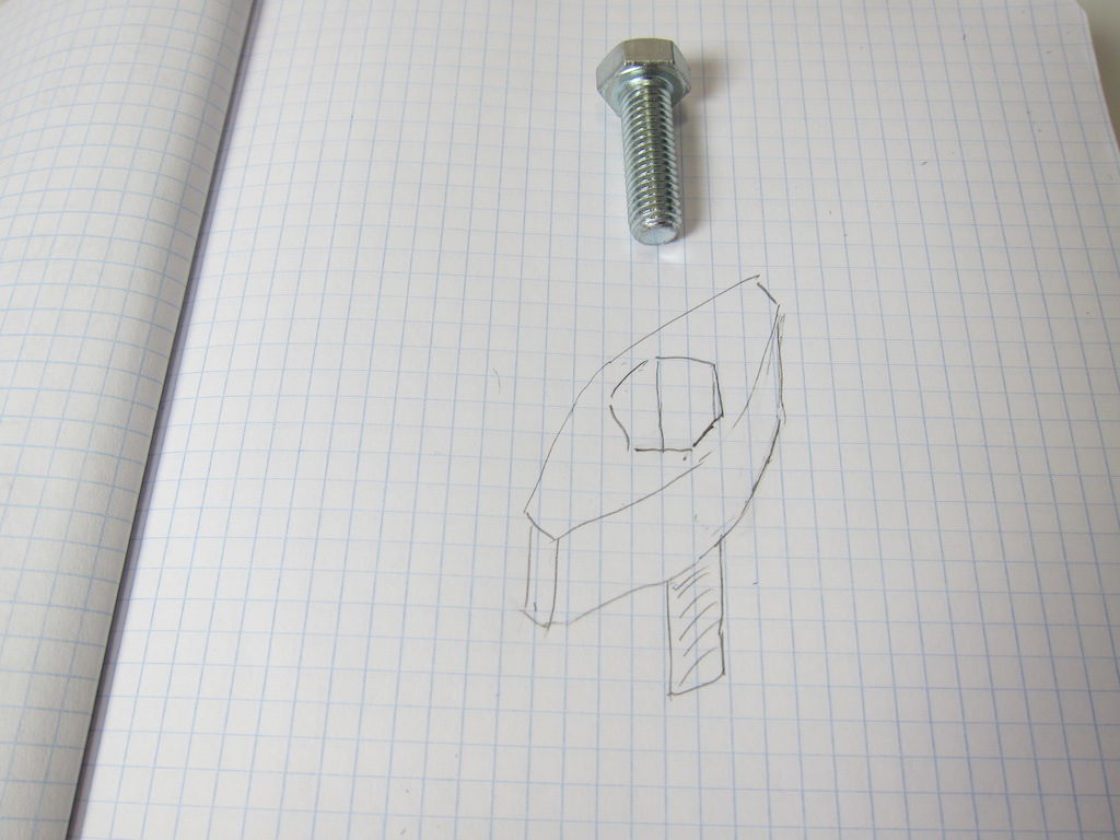
I’m thinking I’ll make a plastic knob that a conventional bolt fits into. Since I’m making my own, I can also try to duplicate the style of the existing knobs on the tripod.

tk_paper_sketch

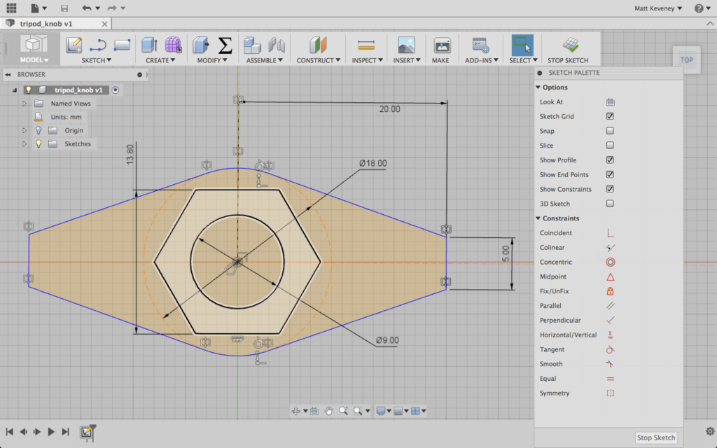
First I create a sketch on the XZ plane with the hex head centered. I create a hole for the threaded part to fit through; a construction circle to which I can align the flat sides of the ‘wings,’ and then the wings themselves. This sketch describes three distinct profiles: the innermost hole; the hex hole, and the wings. Fusion 360 highlights these profiles as you hover with the mouse; in the following screenshot, the hex profile is highlighted.

tk_sketch1

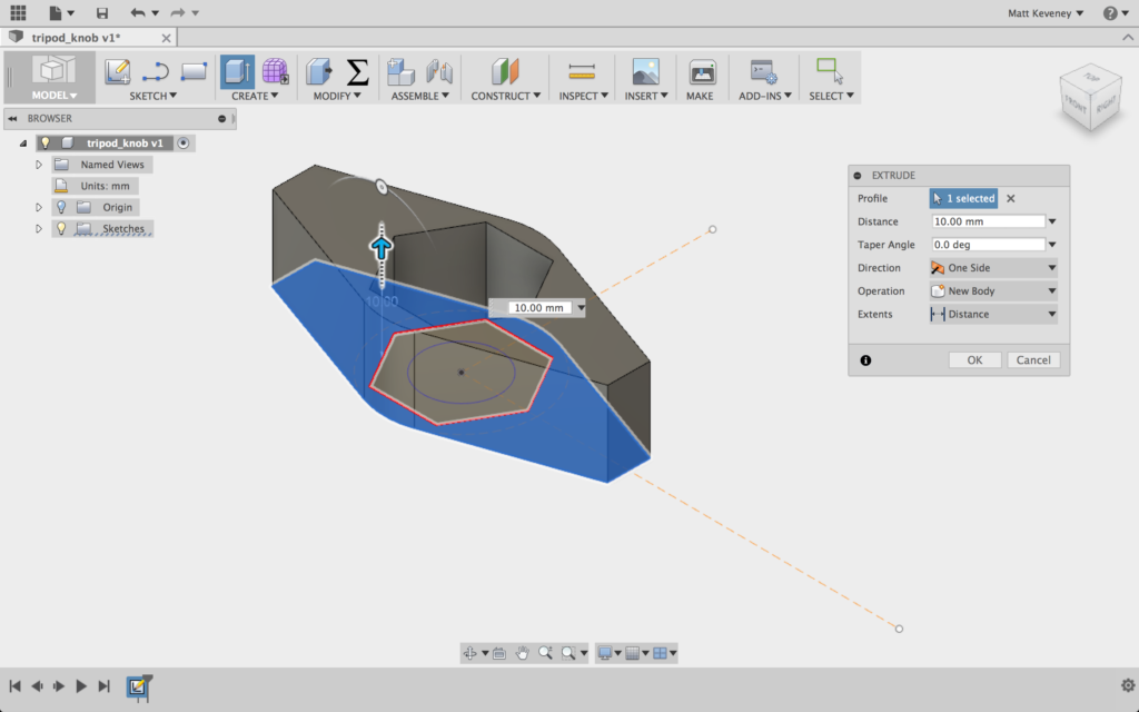
I extrude the outermost profile upward to create the wings.

tk_extrude1

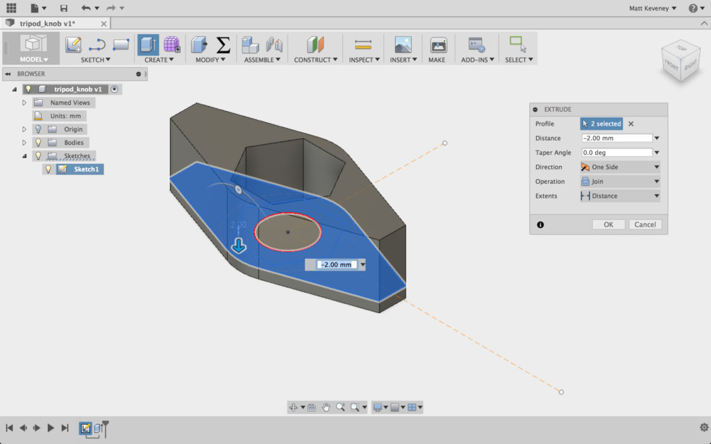
And I extrude the outermost and hex profiles downward slightly to create the flat part that traps the nut. This also extends the wings downward.

tk_extrude2

I could stop right here and have a functional part. If I was in a hurry that’s what I’d do, but I’ll keep going just so I can illustrate a few more Fusion 360 tricks.

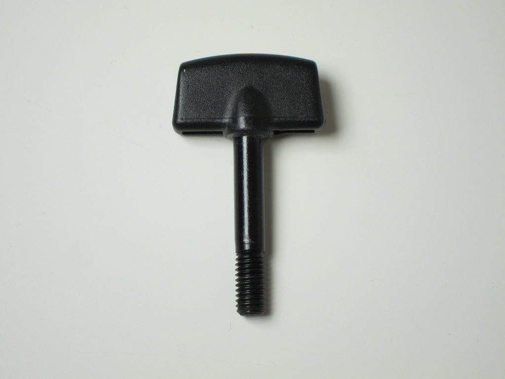
On my tripod’s other wing-knobs the side profile is slightly rounded on top, and has ends that slope inward slightly. Retaining this design detail might make my new part look more like it belongs.

tk_existing_wingnut

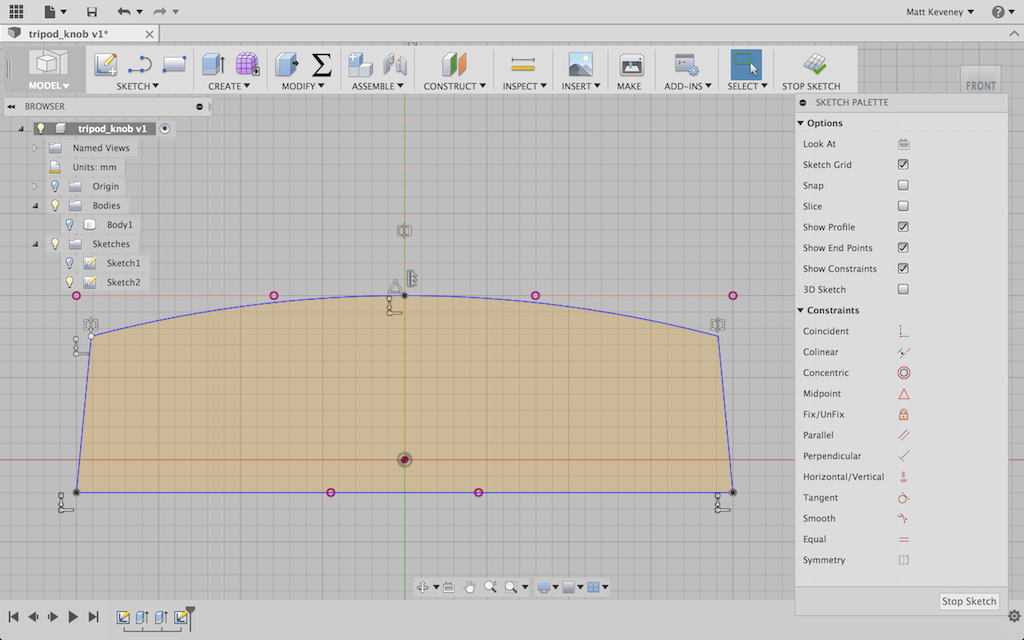
I’ll create another sketch on XY plane for this. Note that this sketch plane bisects the current body; that’s OK. I first project the intersection of the top and bottom face of the body into my new sketch, then hide the body. Then I select the projected lines (the purple ones) and click X to convert them to construction lines. Now I can draw the rest of the sketch, using the construction lines to guide my work.

tk_sketch2

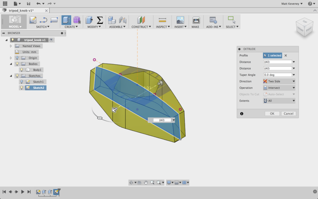
Then I turn the body back on and extrude this profile, using a symmetric direction and the intersect operation.

tk_intersection

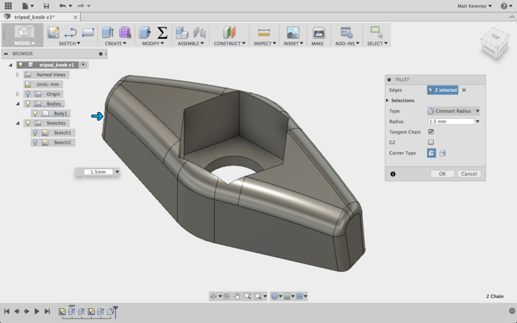
Now, I use the fillet tool to round the edges a bit. I’m a big fan of the fillet tool for parts that get handled frequently; it really makes a big difference in the feel of the part.

tk_filletted

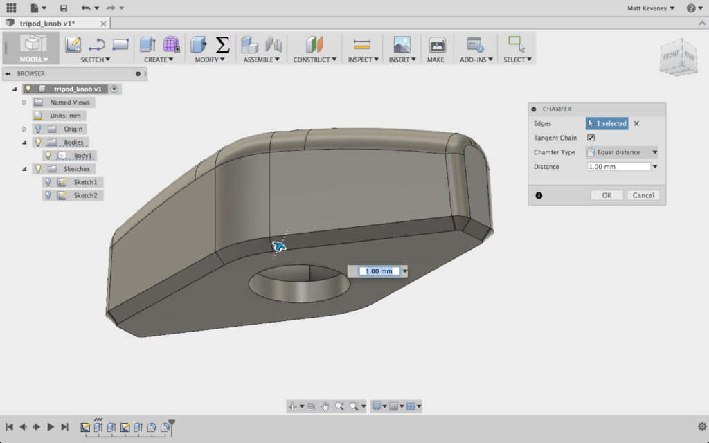
I’m planning on printing this oriented with the hex hole upward. If I fillet the bottom edges of the part, I may get sloppy results, since the start of the fillet curve is over our overhang limit. I’ll simply use the chamfer tool instead.

tk_chamfered

Let’s print it out! I generally use two perimeters and four layers top and bottom. In this case I’ll use 25% fill. I really only use three fill settings: 15%, 25%, and 40%. I don’t think the percentages reflect the density of the part; 40% is nearly solid.

tk_printing

It works!

tk_assembled
tk_inplace