Just a few quick notes to follow-up my last post on Fusion 360 for laser cutting.
Inside-out
Recall that Ray noticed I had made no provision to cut holes in parts before cutting the part free. This can be done in the laser control software (Lasercut 5.3) by creating two layers. Select all the holes for the first layer; the part perimeters for the second layer. Both layers should be configured for cutting with the same power and speed settings.
I noticed that I seemed to be getting proper cut order nonetheless. I inquired about this on the Fusion 360 CAM forum. Sure enough, it turns out that Fusion 360 attempts to order the inner perimeters first by design.
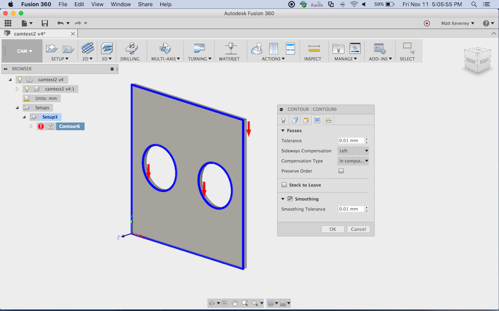
You can manually override the cut order by checking ‘preserve order’ on the ‘passes’ tab of the contour operation (screenshot above). The cuts will then be performed in the order the contours were selected.
You could also create two contour operations, selecting the inside perimeters on the first one. This essentially reproduces the above technique using Fusion 360 instead of Lasercut 5.3. I would prefer this method if I had to carefully control the cut order for a complex model; especially one that might change over time.
But for a complex project there can be a lot of paths to select. It’s a tedious step at best, even without this extra worry. My plan is to let Fusion 360 do its thing and double check with the ‘simulate’ function. So far it hasn’t let me down.
Don’t edit the DXF!
Note that Fusion’s control over the order of operations ends with the DXF file. If you edit the DXF later, by manipulating things within Lasercut or some other tool, all bets are off.
I generally do use Lasercut’s ‘unite lines’ tool before cutting, but this does not seem to affect the cut order. In fact, I’m not sure it’s really necessary. I haven’t tested without performing the ‘unite lines’ step.
Smoothing
I strongly recommend using the ‘smoothing’ feature, also located on the ‘passes’ tab. Without it, Fusion 360 will reduce everything to line segments, greatly expanding the size of the DXF. With smoothing on, ARC objects are emitted where appropriate. The simple example above (a rectangle with two circular holes), resulted in the following file sizes:
Smoothing on:   1166 bytes
Smoothing off: 22538 bytes
Hope that helps. If you want to try it out and need a hand, let me know!